The Phase Shift Oscillator
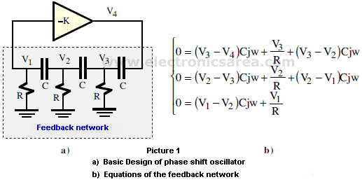
The phase shift oscillator, whose basic structure is described in the picture 1.a has a a negative gain amplifier (-K) and a feedback network consisting of a third order RC section in cascade.
The oscillation condition requires that the feedback network produce a phase shift of 180° to be consistent with the negative gain amplifier which in turn introduces another phase shift of 180°
Picture 1.b shows the equations of the feedback network. From these equations and following a series of operations, we can see that the loop gain is:
The oscillation conditions, establish the value of ƒo and the value of K. They are given by
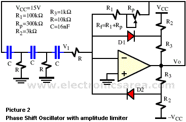
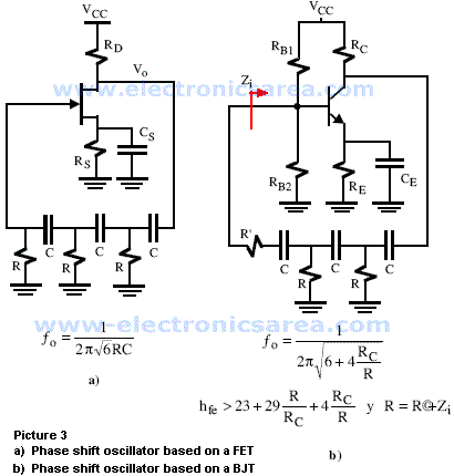
Practical examples of such oscillators are shown in pictures 2, 3.a y 3.b.
On the picture 2 the oscillator is based on an Operational Amplifier whose gain (-Rf/R) is adjusted with the potentiometer Rp and has an output amplitude limiter through diodes D1 and D2. On pictures 3.a and 3.b there are two oscillators using discrete components. The first one is based on a FET amplifier whose gain is:
and the second one is based on a BJT amplifier whose hfe and Zi should verify the relationships shown in the picture with an oscillation frequency dependent on RC.


