Home / Circuits / Timer circuits /
5 to 30 Minute Timer circuit
This 5 to 30-minute timer circuit achieves times ranging from 5 to 30 minutes using the 7555 integrated circuit (CMOS version of the popular 555 timer).
How does the 5 to 30 minute timer circuit work?
The 7555 IC works as a monostable multivibrator, delivering at its output, a positive pulse for a time set by the values of R and C.
Establishing the delay time
The pulse time is given by the formula 1.1 x RC. Where R is the series combination of the 8.2M resistors (see diagram) and C is a capacitor of 33 μF. Obtainable times are 5, 10, 15, 20, 25, and 30 minutes, changing the switch position.
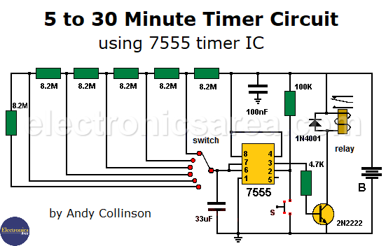
The 7555 timer output (pin 3) is connected to the 2N2222 NPN transistor through the 4.7K resistor. When the output of 7555 goes high, the transistor passes to the saturation state and activates the relay. The relay can control anything, for example, a radio, a lamp, a small alarm, etc. The type of device that the relay can control depends on the current the relay can withstand.
Why do we need to use the 7555 timer?
In order for the 5 to 30 minute timer to work properly, it is important to use the 7555 timer and not the typical 555 IC so you can work smoothly with the 8.2 MΩ resistors. The 33uF capacitor should have little leakage. The 1N4001 diode is used to protect the transistor 2N2222 when the relay is deactivated.
Bear in mind that the times of this timer are not accurate due to possible variations in the values of the elements used (resistors, capacitors)
5 to 30 minute timer parts List
- 1 x 7555 timer
- 1 x 9V battery (B)
- 1 x 33 μF capacitor
- 1 x 100nF capacitor
- 1 x 2N2222 NPN transistor
- 1 x 1N4001 diode
- 6 x 8.2M resistors
- 1 x 100k resistor
- 1 x 4.7k resistor
- 1 x 9-volt coil relay
- 1 x NO (normally open) push button (S)
- 1 x switch (6 positions)
Other circuits that can be useful for you are Time delay circuit using triac & 555 or Light push button circuit with time delay
Notes:
- The power supply (B) to the circuit can have a value between 5 and 15 volts.
- The relay voltage must be the same voltage as the source.
Original circuit by Andy Collinson.
More timer Circuits
- Perfect Square Wave – Formula – Examples
- High current pulse generator
- Electronic Doorbell Circuit (555 & CD4017)
- Automatic Night Light (555 & relay)
- Sound Activated Flash trigger (555 & LM386)
- Off-Delay Timer Circuit using 555 IC
- Time Delay circuit using (Triac & 555 IC)
- 5 to 30-Minute Timer Circuit (7555 IC)
- Long Duration Timer with NOR gates
- Missing pulse detector circuit (555 timer)
- ON-OFF Switch circuit using a 555 IC (PCB)
- Event Sequencer using the 555 timer
")

")

For 7555 CMOS timer, you’d better add a 10nF capacitor between pin 5 and ground, otherwise the noise will likely to turn output into high when you power your switch on, even before you setup your timer switch.
Hello,
Thank you very much. You’re right, we’re going to correct the article.
regards