What is a XOR Gate?
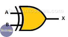
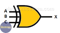
In digital electronics there are special gates. One of them is the XOR Gate or Exclusive OR gate. The images below shows the symbol of a 2-input and 3-input XOR Logic Gate. Understanding the operation of this digital gate is very important to later be able to implement what is called a digital comparator.
If we analyze the truth table of a OR gate, we see that the output is “1” when one or more inputs are “1”. This gate is a little different, and the output is “1” when one or more inputs, but not all, are “1”. We can also say that the output of an XOR gate is “1” when all inputs are “1” or all inputs are “0”.
Another way to find out the output is counting the number of “1” we have at the inputs. If we have an odd number the output is “1”, if not the output is “0”.
2-input and 3-input XOR gate symbols
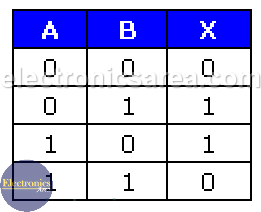
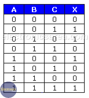
2-input and 3-input XOR gate truth tables
The image below shows the truth table of a 2-input XOR gate. This gate is represented by the following Boolean function: X = A.B + A.B. Unlike the OR gate, this gate has an output is “0” when both inputs are “1”.
If you compare the truth tables of the OR gate and the XOR gate, you can see that the output is “1” when the addition of the inputs is an odd number.
The boolean expression can be written in two ways: X = A.B + A.B or  . The following image shows the truth table of a 2-input exclusive OR gate. It can be seen that the output is “1” only when both inputs have different logic levels. Again it can be seen that the output is “1” when there are an odd number of “1” in the inputs.
In the same way as in the previous case, the 3-input xor gate output is “1” (X = 1) only when the sum of the inputs equals an odd number. See the image below.
This gate is represented by the following Boolean function: X = ABC + ABC + ABC. Unlike the OR gate, this gate has an output is “0” when at least one input is “1”.
A boolean expression for the xor gate can be written in two ways: X = ABC + ABC + ABC or .
The following image shows the truth table of a 3-input XOR logic gate. It can be seen that the output is “1” only when there are an odd number of “1” in the inputs.
Equivalent Circuit
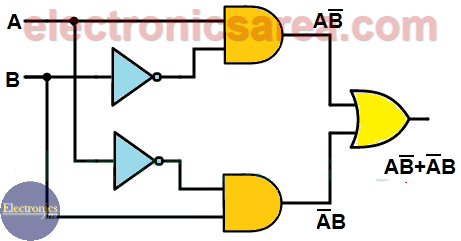
You can also implement the exclusive OR gate with a combination of basic gates. The following diagram shows a two-input XOR gateway implemented with basic gates: AND logic gate, OR logic gate, and NOT gate.
Compare this image with the formula: X = AB + AB
XOR gate application: 3-way Switch
One of the possible uses of this gate is in a 3-way switch, which is used in some long hallways to control the lights from both sides. Looking at the truth table, every change no matter which input is, it always toggles the output.
More Digital Tutorials
- What is the difference between Analog & Digital?
- What is a logic circuit?
- Digital logic levels (high, low, 1, 0)
- The truth table
- Boolean algebra
- Karnaugh Map (K-map)
- Binary number system
- Hexadecimal numbering system
- BCD code – binary coded decimal
- Gray code – Gray code table
- Aiken code – Excess 3 code
- AND gate
- NAND gate
- OR gate
- NOR gate
- NOT gate
- XOR gate
- How to build a NAND gate with transistors & diodes?
- OR & AND logic gates made with diodes
- The combinational circuit
- The sequential circuit
- JK Flip-Flop
- What is a binary decoder?

