Voltage gain and Power Gain on an Amplifier – Explanation and formulas. The decibel expresses a ratio of quantities, not a quantity itself.
Voltage gain and Power Gain on an Amplifier – Explanation and formulas. The decibel expresses a ratio of quantities, not a quantity itself.
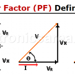
Power factor is the ratio between the energy that is converted into work and the electrical energy consumed in a circuit or device
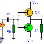
Push – Pull Amplifier
A Push – Pull amplifier is called that way, because it uses 2 groups of transistors and only one works at a time. One group pushes in one direction while the other pulls in another direction. Each group is responsible for amplifying a single phase of the input wave.
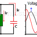
Parallel RC circuit
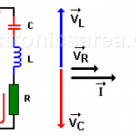
Voltage, Currents, Phasor diagram & Impedance. Voltage is the same on the capacitor and resistor. Current is ahead of the voltage in the capacitor
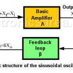
The sinusoidal oscillator basic structure consists of an amplifier (A) and a selective frequency network (ß) connected in a positive feedback loop
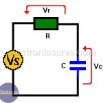
In a series RC circuit, the current through the resistor and the capacitor is the same. The voltage VS is equal to the phasor addition of the voltage drop across the resistor (Vr) and the voltage drop across the capacitor (Vc).
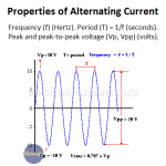
The difference between an alternating current and a direct current is that a direct current only flows in one direction. Alternating current circulates in one direction, then the opposite direction, and repeats this process continuously.
Resonance in RLC Circuits is a special condition for parallel and series RLC circuits, when capacitive reactance and inductive reactance have the same magnitude and cancel each other. This only happens at frequency fo.
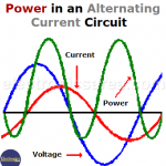
Electric power. Electrical power on a circuit with reactive load (reactance). How to obtain the current in a circuit having resistance and reactance.
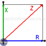
Impedance (Z) shows the opposition to the flow of direct or alternating current. Impedance is the vector addition of resistance (R) and reactance (X).
What is a radian?
The radian is the angle that cover the portion of the circumference which is equal to the length of the radius of the circle
The Crystal Oscillators (Piezoelectric Oscillator) A quartz crystal has a property called: piezoelectric effect. This effect causes, by applying a mechanical pressure on the surface of the crystal, that a voltage is developed on the opposite sides. Similarly, a voltage applied on the faces of the crystal produces a mechanical distortion on their surface. An AC voltage causes mechanical vibration whose […]