Detector Circuits and Projects
Detector Circuits and Projects
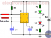
2-LED Temperature Change Indicator with LM35 & 741

This circuit shows us, by means of 2 LEDs, when the sensed temperature is above or below a set limit. When the temperature is above the preset temperature level, LED D1 will light up, and if it is below, LED D2 will light up.
Photodiode Amplifier Circuit – Current-to-Voltage Converter

Very simple circuit that amplifies the current signal generated by a photodiode and transforms it into voltage with a controlled gain
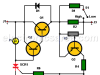
Humidity Sensor circuit
This simple humidity sensor circuit, shows us the humidity level that a ground under test has. To achieve the goal, a couple of probes are used.
High-Speed Electronic Fuse for Solid-state Circuits
The high-speed electronic fuse circuit operates in nearly one-hundredth of a microsecond, making it faster than an ordinary fuse.
Temperature Gauge Circuit Using LM324 (PCB)
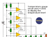
The temperature gauge circuit is implemented using four comparators. We use the LM324 integrated circuit, which has four 741 operational amplifiers (op amps) in a single package.
Blown Fuse Indicator Circuit using one transistor
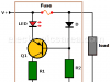
This single transistor blown fuse indicator circuit warns us by lighting a LED when there is a problem in an electrical installation protected by the fuse.
Twilight Switch Circuit
This Twilight switch circuit activates a light, a lamp, a motor, etc., at the time of sunset and performs the reverse process at dawn.
The is an ideal circuit for activating a security light that must be on all night.
Light detector circuit using LDR (automatic night light)
This circuit activates a lighting device through a relay when the intensity of daylight is no longer sufficient. Good for illuminating the main entrance of the house, a display case that needs to be kept lit at night, an unsafe area at night, etc.
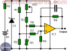
How to make a Light Sensitive Sound Generator Circuit?
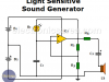
Light Sensitive Sound Generator Circuit – An oscillator circuit may have many applications. The diagram shows how to make it work as a light sensitive sound generator using a LDR and a 741 operational amplifier.
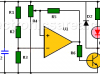
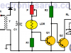
Light activated switch circuit with LDR and Op Amp
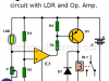
This circuit has many applications. It could act as a photocell and switch off a light in a room or turn on the radio when it is dawning, etc.
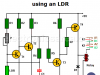
Light Operated Relay Circuit using LDR / Photoresistor
The LDR varies its value (ohms) depending on the amount of light that illuminates it. The more light less resistance and less light more resistance, A potentiometer is used to control the light level that activate the relay
Dark detector circuit using LDR and relay
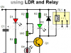
This circuit uses, as a main component, an LDR (photoresistor). An LDR changes its resistance value depending on the amount of light it received. The more light means less resistance, the less light means more resistance.
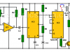
Darkness detector circuit with audio output using 555
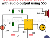
The main elements of this circuit are the 555 integrated circuit, working as an astable multivibrator and an LDR which is used as darkness sensor.
Temperature to Voltage Converter using Thermistor (PCB)
This circuit convert the sensed temperature by a thermistor into a voltage level. The circuit achieves an acceptable performance between 0°C and 24°C
Rain Detector using two Transistors
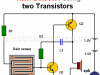
Circuit that aims to alert the beginning of the rainfall. Its few components make it an interesting and easy project.
Lie Detector Circuit Using Two Transistors
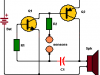
This simple lie detector consists of two transistors and other additional components and can detect if a person does not tell the truth (the person is lying), using two sensors placed directly on the skin.
Electronic sound control Circuit (applause)
This electronic sound control circuit works like a sound activated relay and can activate or deactivate a device connected to it, by two consecutive claps.