Home / Circuits / Controllers /
Heat Control Circuit Using a Thermistor and a TRIAC
This heat control circuit, which uses a thermistor and a TRIAC, is designed to control the temperature of a room. It can do so by using a heat source, such as an electric oven heating element, or a cooling device, such as a fan.
The trigger circuit uses a unijunction transistor (UJT) to introduce a conduction angle to the TRIAC. The size of this angle depends on the room temperature, which is measured using a thermal resistance or thermistor (RT). The thermistor has a value of 2 kilohms at 25 °C.
A bridge diode rectifier and a Zener diode power the circuit and maintain stable voltage for the trigger circuit.
The resistor R2 is adjusted so that the PNP bipolar transistor Q1 does not enter the cutoff state at a given temperature. When Q1 is in the cutoff state, no current charges capacitor C1. Therefore, the UJT and the TRIACs are also in the cutoff state.
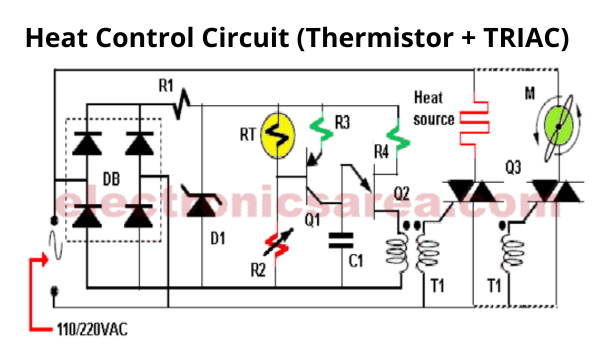
If this transistor is saturated (on), it will charge capacitor C1 and trigger the UJT when the voltage reaches Vp. The time it takes for the UJT to reach the Vp voltage depends on the RT thermistor.
An increase in temperature decreases the value of RT, which consequently decreases the collector current of the transistor by increasing the charge time of the capacitor and decreasing the conduction angle. Conversely, decreasing the temperature increases the driving angle.
To reverse the operation of this circuit and how it responds to temperature, exchange resistors RT and R2.
You may be interested in: Thermistor-Controlled AC Fan Circuit.
List of heat control circuit components
- 1 Sprague Pulse Transformer (T1)
- 1 Rectification bridge MR1121 (DB)
- 1 Zener diode 1N5250A, 20 volts (D1)
- 1 bipolar PNP transistor 2N3905 (Q1)
- 1 UJT transistor 2N4870 (Q2)
- 1TRIAC MAC218A (Q3)
- 1 20k resistor, 1W (R1)
- 1 2K @ 25C thermistor (RT)
- 1 50K potentiometer (R2)
- 1 10K resistor (R3)
- 1 1K resistor (R4)
- 1 0.1 uF (microfarads) capacitor (C1)
The circuit can be powered by either 110 or 220 VAC. The required supply voltage for the heat source and AC motor also affects this.
More Controller circuits
- Water Level Controller using Transistor and Relay
- Automatic Water Level Controler
- Water level controller using NOR gates
- Differential Temperature Controller (PCB)
- Soldering Iron Temperature Controller
- Heat control using thermistor and TRIAC
- Thermistor Controlled AC Fan
- Electronic Thermostat using transistors
- H-Bridge DC Motor Control
- DC motor speed controller using 555
- DC Motor Speed Control with 4049
- Dimmer / AC Motor Speed Controller using TRIAC


