Blown Fuse Indicator Circuit using one transistor
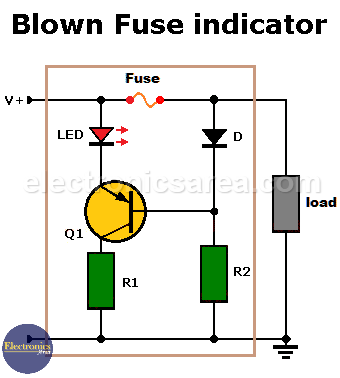
This blown fuse indicator circuit warns us by lighting a LED when there is a problem in an electrical installation protected by the fuse.
It is very important to correct faults in the electrical system of a car, motorcycle or other vehicle as soon as possible.
If you don’t know that a fuse has blown, you may get into trouble when the problem is more difficult to solve. For example, at night or far from a mechanic’s shop.
How does the blown fuse indicator circuit work?
The circuit shown in the diagram consists of only a few elements. The most important is a PNP bipolar transistor that acts as a switch.
Blown Fuse Indicator Circuit using one transistor
– If V+ is present and the fuse is good, the transistor will be in the turn-off region and will not conduct. (Note that the voltage at the base of the transistor is V+ – 0.7 volts) and consequently the LED will not light up.
– When the fuse blows, no current flows through the fuse and the voltage level at the base of the transistor drops to zero volts. The transistor enters saturation (current flows through the emitter and collector), and the LED lights to indicate a problem.
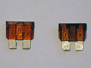
Car_fuses intact and broken
Cqdx, CC BY-SA 3.0, via Wikimedia Commons
There are many fuses in a car’s electrical system. To have a general check of all the fuses, you can connect this circuit in parallel with each fuse. This circuit can also be used in toys, car stereos, and almost any DC or battery circuit.
You may also want to visit this Energy-saving flashing pilot light circuit
Blown Fuse Indicator Circuit Component List
- 1 BC558 or NTE159 PNP Bipolar Transistor (Q1)
- 1 1N4001 or 1N4148 Semiconductor Diode (D1)
- 1 Red LED
- 1 510 Ohm resistor (R1)
- 1 510 K resistor (R2)
Notes:
- The circuit is powered from the same DC source that the load is using.
- It is always advisable to carry spare fuses of each type that the car or motorcycle needs.
You might be interested in: High-Speed Electronic Fuse for Solid-state Circuits
More Detector Circuits
- Light detector circuit using LDR (automatic night light)
- How to make a Light Sensitive Sound Generator Circuit?
- Light activated switch circuit with LDR and Op Amp
- Light Operated Relay Circuit using LDR / Photoresistor
- Twilight Switch Circuit
- Dark detector circuit using LDR and relay
- Darkness detector circuit with audio output using 555
- Temperature Gauge Circuit Using LM324 (PCB)
- Temperature to Voltage Converter using Thermistor (PCB)
- Rain Detector using two Transistors
- 2 LED Temperature Change Indicator with LM35 & 741
- Lie Detector Circuit Using Two Transistors
- Humidity sensor circuit using the 555 timer
- Blown Fuse Indicator Circuit using one transistor
- Electronic sound control Circuit (applause)
- Photodiode Amplifier Circuit – Current-to-Voltage Converter


