Temperature to voltage converter circuit using thermistor
This temperature to voltage converter circuit, convert the sensed temperature by a thermistor into a voltage level. The conversion can be considered linear within an acceptable temperature range. The nonlinearity of the conversion is due to characteristics of the thermistor. The circuit achieves an acceptable performance between 0 °C and 24 °C.
How the Temperature to voltage converter works?
The change must be 0.5 volts per degree Celsius (°C). If this were not so, you must adjust the values of the R4 and R8 resistors (the two resistors must have the same value). The temperature sensor (R5) is a negative coefficient thermistor. (NCT).
If temperature increases, the resistive value of the thermistor decreases, as the voltage across its terminals. As a consequence, the voltage, at the output terminal of the operational amplifier, increases.
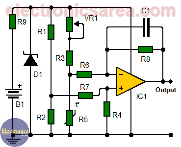
You can experiment with variations on the ranges of temperature, by changing the values of the R1 and R2 resistors (hint: put a 10K pot instead of R2)
How To calibrate the temperature to voltage converter circuit?
To achieve an output of 0 volts, we decrease the thermistor temperature to 0 °C, then we adjust the RV1 potentiometer to ensure that the output voltage is correct.
Temperature to voltage converter circuit list of components
- 1 741 operational amplifier (IC1)
- 3 10K resistors (R1, R2, R3)
- 2 680K resistors (R4, R8)
- 2 100K resistors (R6, R7)
- 1 470 ohm resistor (R9)
- 1 10K negative coefficient thermistor (NCT) (R5)
- 1 10K potentiometer (VR1)
- 1 1N4736, 6.8V zener diode (D1)
- 1 100 nF (nanoFarad) capacitor (C1)
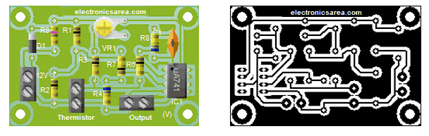
Printed Circuit Board (PCB)
A suggested printed circuit board and approximate appearance of the final circuit are shown.
More Detector Circuits
- Light detector circuit using LDR (automatic night light)
- How to make a Light Sensitive Sound Generator Circuit?
- Light activated switch circuit with LDR and Op Amp
- Light Operated Relay Circuit using LDR / Photoresistor
- Twilight Switch Circuit
- Dark detector circuit using LDR and relay
- Darkness detector circuit with audio output using 555
- Temperature Gauge Circuit Using LM324 (PCB)
- Temperature to Voltage Converter using Thermistor (PCB)
- Rain Detector using two Transistors
- 2 LED Temperature Change Indicator with LM35 & 741
- Lie Detector Circuit Using Two Transistors
- Humidity sensor circuit using the 555 timer
- Blown Fuse Indicator Circuit using one transistor
- Electronic sound control Circuit (applause)
- Photodiode Amplifier Circuit – Current-to-Voltage Converter