Home / Circuits / Battery related /
Car Battery Monitor Circuit
This car battery monitor circuit is very simple and very interesting. How many times have you found that the car does not start because the battery is discharged? This circuit uses 3 transistors and some additional elements to show the level of charge of the battery.
How does the car battery monitor work?
The circuit diagram has 2 LEDs (light-emitting diodes). If the green LED is ON, the battery is charged; if the red LED is ON, the battery needs to be charged.
When the battery charge is OK
When the voltage at the variable end of the potentiometer R1 exceeds the voltage, which is the sum of the base-emitter voltage of Q1 plus the voltage of the zener diode (D1) plus the voltage drop in R2, the transistor Q1 becomes saturated and a current passes through resistor R3 and the green LED lights up, indicating that the battery charge is OK.
When the battery needs to be charged
The red LED turns on in the opposite case, when the voltage, which is the sum of the base-emitter voltage of Q2 plus the voltage of the zener diode (D2) plus the voltage drop on the R5 resistor, is less than the voltage in the variable end of the R4 potentiometer, indicating that the battery has a low charge.
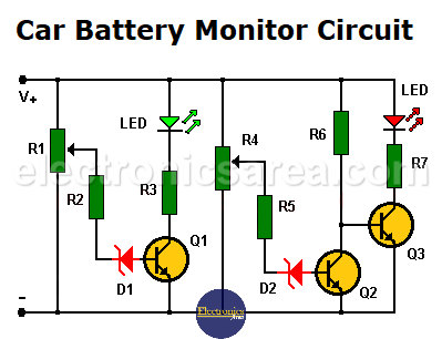
- When transistor Q2 is saturated, the battery charge is OK, and transistor Q3 is in cutoff.
- When transistor Q2 is in cutoff, the battery charge is not OK, and transistor Q3 is saturated.
Transistor Q2 is used as an inverter.
How do you set the voltage that turns on and the voltage that turns off each LED?
Very simple. We connect the circuit to a variable voltage source (to simulate the different possible voltages at the battery terminals). Then the potentiometers (R1 and R4) are tuned so that …
For example:
The green LED lights only when the voltage is above 13 volts and
The red LED will light only when the voltage is below 11.5 volts.
If none of the two LEDs light up, it means that the battery voltage is between the two limit voltage values set by the potentiometers.
A car battery should never have a voltage lower than 12 volts nor a voltage greater than about 14.4 volts. With the help of these data, the circuit can be well calibrated.
List of circuit components for the Car Battery Monitor
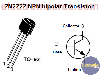
- 3 NPN 2N2222 or similar transistors (Q1, Q2, Q3)
- 2 10 KΩ potentiometers (R1, R4)
- 2 33 KΩ resistors (R2, R5)
- 2 390 Ω (ohms) / 0.5 watts resistors (R3, R7)
- 1 39 KΩ resistor (R6)
- 2 6 to 8 volts / 0.5 watts (D1, D2)
- 2 LEDs (1 green and 1 red).
More battery monitor circuits:
Battery Monitor Circuit using 4 LEDs
Battery Charge Monitor Circuit with LM3914 IC (10 LEDs)
")

")
