Home / Circuits / Battery related /
Battery Charge monitor with LM3914
This 12V battery charge monitor circuit shows, with colored LEDs, the charging process of a typical 12-volt car battery. Once the circuit is built, it is necessary to make some final adjustments with a digital multimeter, so that it works correctly. See: measure voltage in direct current (DC).
To achieve our goal, we use the LM3914 integrated circuit. The LM3914 is an analog voltage meter and can control up to 10 individual LEDs. These LEDs can be displayed in “bar mode” or “point mode” and can be selected by connecting pin 9 of the integrated circuit to VCC or 0 volts.
The LM3914 is designed to display the value of an electrical signal, comparing it to a preset reference voltage value.
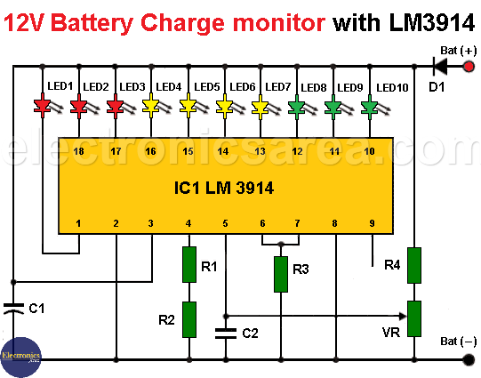
12V Battery Charge Monitor Circuit with LM3914 IC
Battery Charge Monitor Operation and Adjustment
- Put 12.65 Volts between the positive terminal and the negative terminal of the circuit.
- Adjust the potentiometer (VR) until LED 10 lights up.
- Then decrease the voltage little by little, and you will see that the other LEDs will light up in sequence until they reach LED1.
- When only LED1 is on, there will be a voltage of approximately 11.85 V across the circuit terminals.
With a voltage of 12.65 V or more the battery is fully charged and with a voltage of 11.85 V or less the battery is considered discharged.
- When LEDs 8, 9 or 10 are on, they indicate that the battery charge is greater than 50%.
- When LEDs 4, 5, 6 or 7 are on they indicate that the charge is between 30 and 50%.
- When LEDs 1, 2 or 3 are lit, they indicate that the battery charge is less than 30%.
LM3914 Dot/Bar Display Driver
This circuit consumes less than 10 mA, as long as the “point mode” is chosen. Which means that only one LED lights up at a time. If the “bar mode” is used, the current consumption is higher.
The intensity of illumination of the LEDs can be changed by modifying the value of resistor R3. If the value of resistor R3 is increased, the brightness of the LEDs decreases and in turn reduces the current consumption.
Diode D1 is used to prevent a reverse polarity connection.
Circuit component list
- 1 LM3914 integrated circuit (IC1)
- 1 1N4007 semiconductor diode (D1)
- 1 150 K resistor (R1)
- 1 18 K resistor (R2)
- 1 5.6 K resistor (R3)
- 1 56 K resistor (R4)
- 1 10 K potentiometer (VR)
- 1 47 uF / 16V capacitor (C1)
- 1 0.1 uF (microfarads) capacitor (C2)
- 3 red LEDs
- 4 yellow / amber LEDs
- 3 green LEDs
More battery monitor circuits:
Car battery monitor circuit using 2 LEDs
Car Battery Monitor Circuit using 4 LEDs


")