Shadow detector alarm circuit with 2 LDRs
This shadow detector alarm circuit detects if there is a difference of lighting between two photoresistors, and sends an audible and visual warning. Shadow detector alarms, that use two LDRs, are more reliable than those that use only one.
How the Shadow detector alarm circuit works?
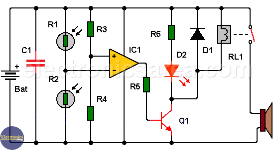
The main elements of this circuit are two LDRs and an operational amplifier that works as a comparator.
The non inverting input of the operational amplifier is set to 4.5 volts, using a voltage divider formed by R3 and R4 resistors. The inverting input of the operational amplifier has a voltage set by the voltage divider formed by the LDRs: R1 and R2.
Shadow detector alarm circuit with two LDRs
In normal lighting conditions (no shadow), the two LDR receive the same amount of light, and the output of the operational amplifier has a low voltage level. When one photoresistor (in this case: R1) receives less light than the other, the voltage at the inverting input of the operational amplifier, goes lower than the non-inverting input.
When this happens, the voltage at the output of the operational amplifier goes high. Then the output voltage of the operational amplifier enable the transistor Q1 (it goes into saturation) to turn the LED on and activates the relay. LED gives a visual warning and relay activates the audible warning.
-

- 741 op amp pinout
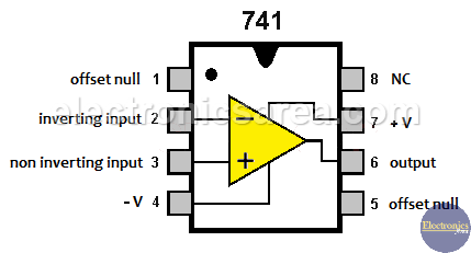
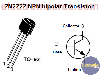
741 Op Amp & 2n2222 transistor Pin Out
It is advisable to place a semiconductor diode (D2) in parallel with the relay, as shown in the diagram, to protect the transistor Q1.
Notes:
– The circuit uses a 9 volt battery or a power supply of the same voltage.
– LDRs should be placed with a separation of no more than 3 cm between them.
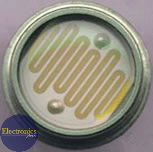
LDR (Light Dependent Resistor)
Shadow detector alarm circuit components
- 1 LM741 operational amplifier (IC1)
- 2 LDRs (photoresistor) (R1, R2)
- 1 2N2222 NPN transistor or similar (Q1)
- 1 1N4007 semiconductor diode (D1)
- 1 red LED (D2)
- 1 9 volt relay (RL1)
- 2 10K resistors (R3, R4)
- 1 1K resistor (R5)
- 1 470 resistor (R6)
- 1 100 nF (nanoFarad) capacitor (C1)
")

")
