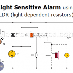
This alarm activates when the illumination level changes from almost total darkness to a moderately high illumination level. When this happens the alarm is locked and the alarm signal, be it a light or a sound, remains active.
This alarm activates when the illumination level changes from almost total darkness to a moderately high illumination level. When this happens the alarm is locked and the alarm signal, be it a light or a sound, remains active.
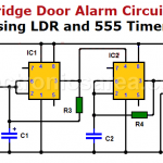
Refrigerator door alarm circuit with two 555 timers
This refrigerator door alarm circuit alerts you when the door has been left open. Very important, because the power consumption increases when this happends. It uses the popular 555 timer IC
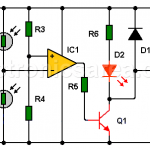
Shadow detector alarm circuit with two LDRs
This circuit detects if there is a difference of lighting between two LDRs, and sends an audible and visual warning. Circuits that use two LDRs are more reliable than those that use only one.