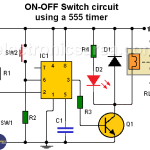
This circuit has many applications on places where it is necessary to activate and deactivate (connect and disconnect) an electrical or electronic device.
This circuit has many applications on places where it is necessary to activate and deactivate (connect and disconnect) an electrical or electronic device.
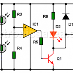
Shadow detector alarm circuit with two LDRs
This circuit detects if there is a difference of lighting between two LDRs, and sends an audible and visual warning. Circuits that use two LDRs are more reliable than those that use only one.