Temperature Alarm using thermostats
Before explaining how a temperature alarm using thermostats works, let’s see what a thermostat is.
What is a thermostat?
There are two types of thermostats. Mechanical thermostats and digital thermostats. In our alarm using thermostats circuit, we will use simple mechanical thermostats.
A thermostat is a device that is intended to control a heating or a cooling system, such as an air conditioner, to maintain the desired temperature within certain ranges.
A thermostat can turn on the heating system when the room temperature is too low, or can also activate the cooling or air conditioning system when the temperature is too high.
How does the temperature alarm using thermostats work?
This simple alarm using thermostats circuit can be used on places where we must detect overheating. For example, a house, a warehouse, etc. The diagram shows an alarm that uses 3 thermostats, and a one, two (NO) contact relay. Thermostats are normally open (NO) type and are connected in parallel.
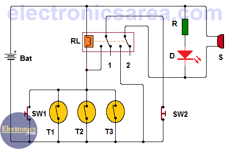
This group of 3 thermostats are connected in series with one relay contact (1), which, when closed, locks the relay itself, memorizing the alarm signal. The second relay contact (2) connects the warning bell or alarm sound. Normally all contacts of the thermostats are open, the relay is not energized and there is no alarm sound.
When the temperature rises more than usual, one or more thermostats contact get closed, then the relay is energized, and the alarm sound is on. Note that there is a switch (SW1) in parallel with thermostats, in order to test the circuit.
When the relay is energized, even momentarily, it locks itself up, the alarm sound is activated and remains on this state, thus the alert signal is maintained. The circuit has a NC switch (SW2) in series with the contact (2) relay.
Pressing the Sw2 button, the relay is disabled and the alarm returns to its standby state. This happens, when all contacts of the thermostats are open, otherwise it will continue ringing.
The entire alarm system is connected to a 12VDC battery or a power supply of the same voltage and has no power consumption on its standby state.
You may also like: Fire alarm with thermostats and SCR.
List of circuit components
- 3 NO (normally open) common mechanical thermostats (T1, T2, T3)
- 1 NO switch (SW1)
- 1 NC (normally close) switch (SW2)
- 1 12V dual (NO) contact relay (RL)
- 1 12 volt siren or alarm bell (S)
- 1 1K resistor (R)
- 1 red LED (D)
More circuits diagrams like this in the alarm projects main page.
Other temperature alarms you may like:
- Over-temperature alarm using op amp
- Car Temperature Alarm using 741 & 555 ICs
- Over temperature alarm circuit using Thermostat
- Temperature alarm circuit with Op. Amp.


")