Home / Transformers /
The Impedance-matching Transformer
An impedance matching transformer is used to couple an antenna to transmission and/or reception equipment. It was widely used in the coupling of the antenna to the analog television and by radio amateurs. Audio amplifiers that use tubes use this coupling transformer to couple speakers with low impedance to vacuum tubes with high impedance.
How does the impedance matching transformer work?
A transformer can be used to match impedance. Assuming that the coupling between the primary and the secondary winding is ideal, the coupling coefficient “k” is 1. If the transformer is not ideal, the coupling coefficient “k” value is less than 1.
Then:
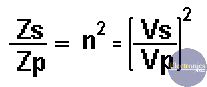
where:
- Zp is the reflected impedance into the primary winding when a load (Zs) is connected to the secondary winding.
- Zs is the reflected impedance into the secondary winding when a load (Zp) is connected to the primary winding.
- N is the turns ratio between the primary and the secondary winding.
n = Vs/Vp = Ip/Is
Impedance matching transformer examples
Example #1: You have an 80-ohm load connected to the secondary winding of a transformer, and the value of n is 3 (N=3). What will be the reflected impedance to the primary winding?
Using the above formula: Zp = Zs/n2. Then: Zp = 80/32 = 80/9 = 8.89 ohms.
Example #2: Let’s suppose we have a 4-ohm load connected to an AC voltage supply with a 400-ohm internal resistance. If they are directly connected, we would not have a maximum power transfer from the power source to the load, because the internal resistance and the load have different values.
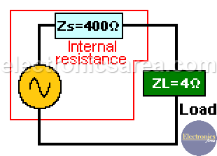
To solve the problem, we use an impedance matching transformer between the voltage supply and the load.
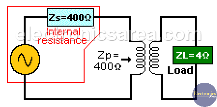
This impedance-matching transformer must have the proper winding relationship to get the resistance of the 4-ohm load to be reflected as if it were 400 ohms to the voltage source. See the second picture above. The equivalent circuit is on the picture below.
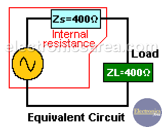
In this case the internal resistance and the resistance reflected from the secondary winding into the primary of the transformer are equal, and there is a maximum power transfer.
n2 = Zs/Zp = 4/400 = 0.01; this means that n = 0.1.
From the following formula, n = Vs/Vp, we find that Vs = nVp. Then Vs = 0.1Vp, or Vp = 10Vs. Then we need a transformer with 10 more times as many spires on the primary winding as in the secondary one.
More Transformer Tutorials
- Ideal Transformer Working Principle
- Transformer Turn Ratio (K)
- Impedance matching Transformer
- Autotransformer
- Transformer Structure
- Power Transformer usage
- Equivalent transformer circuits (power, audio, video and RF)
- Why is the core of a transformer laminated?
")

")
