Light activated switch circuit
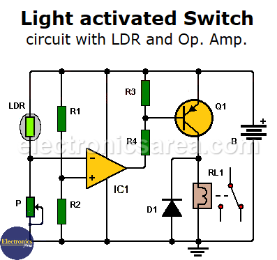
This light activated switch circuit with LDR and an Operational Amplifier has many applications. It could act as a photocell, to switch off the light in a room or turn on the radio when it is dawning, etc.
How the Light activated switch circuit works?
The LDR value in ohms varies depending on the amount of incident light upon it. A network of two resistors (R1 and R2) of equal value, causes that the voltage at the non-inverting terminal of the operational amplifier be 6 or 4.5 volts depending on the battery voltage (12 V or 9 V)
When the LDR is not lit, its resistance is high, causing the voltage at the non-inverting terminal of the op amp to drop below 6 / 4.5 volts. The output of the op amp will be high, transistor Q1 will not conduct, the relay will not receive voltage and will not turn on.
When the LDR is illuminated, the value of the photoresistor decreases and the voltage between its terminals also decreases. This decrease in voltage causes the voltage at the inverting terminal of the operational to increase beyond 6 / 4.5 volts.
The op amp output goes low causing transistor Q1 to conduct (saturate), the relay receives voltage activating any device such as lights, radio, coffee pot, etc.
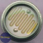
Photoresistor – LDR
The value of the LDR is not critical. The potentiometer P is regulated so that it has the same resistive value as the LDR under normal conditions. The battery can be 12 or 9 volts.
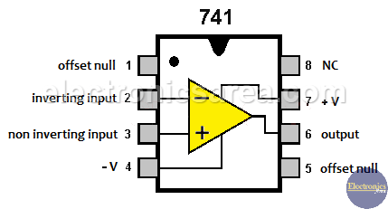
- 741 op amp pinout
Another light activated circuit you can see is the light operated relay circuit using LDR.
List of circuit components
- 1 741 operational amplifier (IC1)
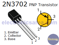
- 1 2N3702 PNP transistor or equivalent (Q1)
- 2 10 K resistors (R1, R2)
- 2 1.2 K resistors (R3, R4)
- 1 potentiometer with a value approximately twice the value of LDR (P)
- 1 1N4001 semiconductor diode or equivalent (D1)
- 1 LDR: any value
- 1 9 volts relay (Bat = 12V) or 6 volts relay (Bat = 9V), with the winding resistance as high as possible, (500 ohms or more)
Notes:
- LDR = photoresistor
- The value of LDR is not critical.
More Detector Circuits
- Light detector circuit using LDR (automatic night light)
- How to make a Light Sensitive Sound Generator Circuit?
- Light activated switch circuit with LDR and Op Amp
- Light Operated Relay Circuit using LDR / Photoresistor
- Twilight Switch Circuit
- Dark detector circuit using LDR and relay
- Darkness detector circuit with audio output using 555
- Temperature Gauge Circuit Using LM324 (PCB)
- Temperature to Voltage Converter using Thermistor (PCB)
- Rain Detector using two Transistors
- 2 LED Temperature Change Indicator with LM35 & 741
- Lie Detector Circuit Using Two Transistors
- Humidity sensor circuit using the 555 timer
- Blown Fuse Indicator Circuit using one transistor
- Electronic sound control Circuit (applause)
- Photodiode Amplifier Circuit – Current-to-Voltage Converter


