Home / Circuits / Controllers /
DC Motor Speed Controller Using PWM (Pulse Width Modulation)
This DC motor speed controller uses a 4049 hex buffer inverter circuit to adjust the speed of small, three- or six-volt DC motors often found in toys and small electronic devices.
The speed of a DC motor is typically controlled by adjusting the supply voltage. Another method of achieving this with a constant voltage is to use pulse width modulation (PWM) techniques to control the time that the voltage is applied to the DC motor.
IIn this way, the speed of the motor only depends on an oscillator that applies adjustable-width voltage pulses. The wider the pulse, the faster the motor turns.
Operation of DC Motor Speed Controller
There are many ways to build an oscillator to control the speed of a DC motor. In our circuit, we use the 4049 integrated circuit. This IC contains six inverters. Two of these inverters are used to create the oscillator.
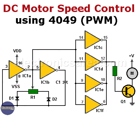
DC Motor Speed Controller Using PWM (4049 IC)
DC motor speed controller using PWM
The frequency of this oscillator is controlled using a 1 MΩ potentiometer, and the oscillation frequency can be approximated by the following formula: 1/(1.4RC), where R is the potentiometer’s resistance (R1), and C is the capacitor’s capacitance (C1). See the image above.
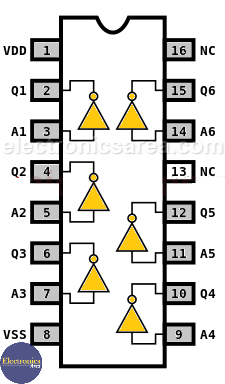
Pinout for the 4049 Hex Inverter Buffer IC
The output signal of this oscillator is connected to the inputs of four inverters that are placed in parallel. These inverters supply sufficient current to the base of transistor Q1.
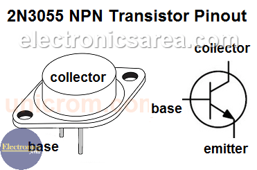
Pinout of the 2N3055 NPN transistor
The transistor operates in the cutoff and saturation regions.
- In the saturation region, the supply voltage is applied to the motor.
- When the transistor is in the cutoff region, the voltage between the motor terminals is zero.
Therefore, increasing the amount of time that the transistor is saturated increases the speed of the motor.
Circuit Component List:
- 1 x CMOS CD4049 IC with six inverter buffers (IC1).
- 1 x 2N3055 NPN transistor (Q1).
- Two 1N914 semiconductor diodes (D1 and D2).
- 1 x 1 kΩ resistor (R2).
- 1 x 1M potentiometer (R1).
- 1 x 0.02 microfarad (μF) capacitor (C1).
- 1 x 6V DC motor (max.) (M).
More Controller circuits
- Water Level Controller using Transistor and Relay
- Automatic Water Level Controler
- Water level controller using NOR gates
- Differential Temperature Controller (PCB)
- Soldering Iron Temperature Controller
- Heat control using thermistor and TRIAC
- Thermistor Controlled AC Fan
- Electronic Thermostat using transistors
- H-Bridge DC Motor Control
- DC motor speed controller using 555
- DC Motor Speed Control with 4049
- Dimmer / AC Motor Speed Controller using TRIAC


