
Home / Circuits / Battery related /
4-LED Battery Monitor Circuit
This simple battery monitor allows us to know the voltage of the battery at all times. To achieve this, an LM324 IC (quadruple operational amplifier), a zener diode, and 4 LEDs are used.
LEDs are placed somewhere on the dash of the car. Each LED has a label indicating the battery voltage at that time.
The circuit is designed so that:
- 1st LED (red) lights up when the battery has 11V
- 1st and 2nd LEDs light up when the battery has 12V
- 1st, 2nd and 3rd LEDs light up when the battery has 13V
- 1st, 2nd, 3rd, and 4th (all) LEDs light up when the battery has 14V or more.
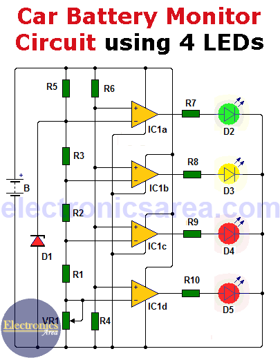
What is the information that the circuit LEDs show?
- If the battery has 11 or 12 volts, it needs to be charged.
- If it has 13 volts, it is in acceptable condition.
- If it has 14 volts, it is fully charged.
The colors of the LEDs indicate the status.
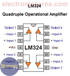
How does the battery monitor circuit work?
The main components of the battery monitor circuit are operational amplifiers, which are used as comparators.
The inverting inputs of the operational amplifiers are set to fixed predefined voltages (5.1V, 4.8V, 4.4V, and 4.1V) using a Zener diode (D1) and a resistor network (R1, R2, R3, and potentiometer VR).
The potentiometer VR is used to make minor adjustments to the above voltages, which may vary because the resistors have no exact values.
The positive terminal of the battery is connected to the non-inverting terminal of the operational amplifiers via the voltage divider formed by resistors R4 and R6. Depending on the battery voltage, the voltage at the non-inverting terminal of the operational amplifier varies and delivers a high voltage level at the output of the comparator, lighting the LED.
List of components of the battery monitor circuit
- 1 LM324 IC (4 op. amps. on a chip) (IC1)
- 1 5.1 volt zener diode, 1/4 watt (D1)
- 4 LEDs (D2, D3, D4, D5) (2 red, 1 yellow, 1 green)
- 1 10 kΩ potentiometer (VR)
- 3 680 ohm resistors (R1, R2, R3)
- 1 10 kΩ resistor (R4)
- 1 1.2 kΩ resistor (R5)
- 1 15 kΩ resistor (R6)
- 4 1 kΩ resistors (R7, R8, R9, R10)
More battery monitor circuits:
Car battery monitor circuit using 2 LEDs
Battery Charge Monitor Circuit with LM3914 IC (10 LEDs)


