
Home / Power Supplies /
Internal Resistance of a Voltage Source
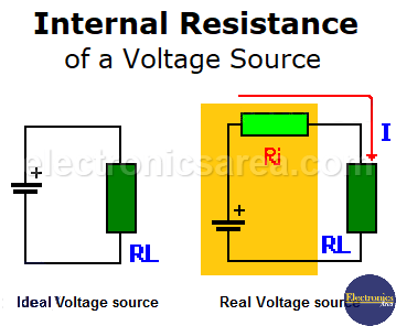
Voltage sources, whether batteries, generators, or others, are not ideal (perfect). A real voltage source is composed of an ideal voltage source in series with a resistance called internal resistance. This resistance does not really exist so that we can see it. It is a resistance deduced by the behavior of the real voltage sources.
See the diagrams of the ideal voltage source and the actual voltage source below.
- VI = Internal resistance voltage.
- VL = Load resistance voltage.
- RI = Internal resistance.
- RL = Load resistance.
Taking the following values: I = 4 amperes, RI = 3 ohms, and RL = 5 ohms.
- Voltage drop on the internal resistance: VI = I x RI = 4 amps x 3 ohms = 12 volts
- Voltage drop on the load resistor: VL = I x RL = 4 amps x 5 ohms = 20 volts
The total voltage drop will be VI + VL = 12 V + 20 V = 32 volts (equal to the voltage of the ideal source) (Kirchhoff voltage law).
It can be clearly seen that only 20 of the 32 volts are applied to the load (RL); the remaining voltage is lost in the internal resistance. Frequently, this voltage (VL = 20 volts) is called terminal voltage because it is measured at the terminals of the voltage source.
How is internal resistance obtained?
To obtain the internal resistance in a voltage source, these steps must be followed:
- The voltage at the terminals of an uncharged voltage source is measured. The measured voltage will be VNL (voltage without load)
- A load is connected to the voltage source, and the voltage is measured. The measured voltage will be VL (voltage with load)
- The current of the source with a load is measured. The measured current will be I
Once these values are available, the following equation is applied: RI = (VNL – VL) / I (1)
For example:
If VNL = 12 volts, VL = 11.8 volts, and I = 10 amperes, then the internal resistance is RI = (12V – 11.8V) / 10A = 0.02 ohms.
From the last equation (1), we can get VL = VNL – (I x RI), so…
If the electric current I grows to 25 amps (meaning that the load resistor has a smaller value), the load voltage is VL = 20 volts – (25 amps x 0.02 ohms) = 11.5 volts.
We can conclude that the more electric current the load (RL) demands, the lower the terminal voltage due to the greater voltage drop in the internal resistance (RI).
Power transfer between a voltage source and a load is at its most efficient when the resistance of the load matches the internal resistance of the voltage source.
You may be interested in:
More Power supply tutorials
- Power Supply – block diagram (AC – DC conversion process)
- Voltage regulators – linear & switching
- Zener diode voltage regulator circuit Design
- Transistorized voltage regulator (zener & transistor)
- Current limiter using transistor & resistor
- Transformerless power supply
- How does a battery work?
- Types of Cells / Batteries
- Internal resistance of a voltage source


