
Home / Power Supplies /
Transistorized voltage regulator using a zener diode
Why use a transistorized voltage regulator? If we use a half-wave or a full-wave rectifier, we can convert an AC voltage into a DC one. This converted voltage is unregulated because the output voltage is not constant and can change due to variations of the load value.
To reduce these variations, we connect a regulator circuit in series with the unregulated output. These circuits reduce the ripple voltage from the output of unregulated sources, and the final voltage varies very little with load variation.
The Zener diode and transistor voltage regulator
This circuit delivers on its output a voltage set by the zener diode voltage minus 0.7 volts. The 0.7 volts is the base-emitter voltage drop (VBE) on the transistor. So the output voltage is Vout = Vz – Vbe = Vz – 0.7V.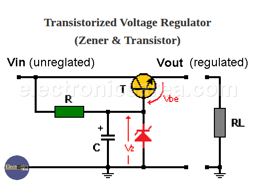
Transistorized Voltage Regulator (Zener & Transistor)
How the Zener and transistor voltage regulator work
- The collector-emitter voltage varies constantly as the input voltage (Vin) changes in order to maintain the constant voltage at the output (Vout).
- The voltage in the Zener diode does not vary much with the change of the current passing through it, so the output voltage of the regulator will vary slightly with the variation of the load (RL).
- In this type of voltage regulator, the Zener diode sets the reference voltage, and the transistor functions as a pass-through current amplifier for the load.
You can set as many different voltage outputs as you want, changing the Zener diode with another with a different voltage. The transistor must withstand the desired maximum amount of current.
For example, If you want a 5V, 500 mA (0.5A) Zener and transistor power supply.
We can use the 1N4735A (5.6 volts) zener diode, the TIP41 bipolar transistor, and a 560-ohm 1/2-watt resistor.
You may also like:


