Twilight switch circuit with Op. Amp. and LDR
This Twilight switch circuit activates a light, a lamp, a motor, etc., at the time of sunset and performs the reverse process at dawn. This is an ideal circuit for activating a security light that must be on all night.
How the Twilight switch circuit work?
This circuit uses an operational amplifier, configured as an inverting amplifier. The circuit uses an LDR as a light sensor. An LDR has very low resistance when exposed to a high intensity light and a very high resistance when it is in the dark.
Resistors R1, R2 (LDR) and R3 form a voltage divider. When the LDR (R2) is illuminated, the voltage at its terminals decreases and the voltage level at the inverting terminal of the operational amplifier decreases.
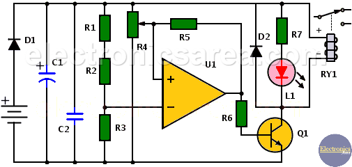
Twilight Switch Circuit
The positive terminal of the operational amplifier is connected to a potentiometer in order to adjust the level of darkness that will make the op amp output goes high.
When the natural light decreases, the value of resistor R2 increases, as the voltage at its terminals. This causes the voltage across the resistor R3 to decrease, causing the operational amplifier output to goes high. This activates the relay and turns ON the LED.
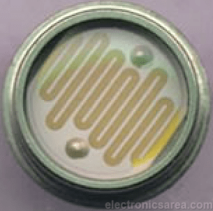
LDR (light Dependent Resistor)
When we are in darkness and daylight returns, the reverse process begins. The value of the LDR decreases, the voltage across resistor R3 increases, exceeding the set voltage in the non-inverting terminal of the Operational Amplifier. This causes the output of the operational amplifier goes to a low level, deactivating the relay and turning off the LED.
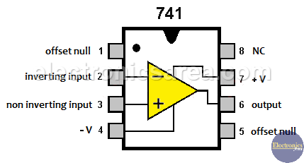
Pin diagram of IC 741 Op Amp
It is very important to prevent the LDR to be illuminated by sources other than natural light. This would be an undesired effect. For example: a Flashlight illuminating the LDR, will turn off the lamp, the motor, or whatever, when it is still dark.
List of components for the Twilight switch circuit
- 2 1K resistors (R1, R7)
- 1 LDR (R2)
- 1 100K resistor (R3)
- 1 100K potentiometer (R4)
- 1 220K resistor (R5)
- 1 10K resistor (R6)
- 1 BC337 NPN transistor
- 1 100uF electrolytic capacitor. 18 volts or more.
- 1 100nF capacitor.
- 2 1N4001 semiconductor diodes (D1, D2)
- 1 Red LED (L1)
- 1 LM741 Operational Amplifier (U1)
- 1 12V relay dual output (NO and NC) (RY1)
More Detector Circuits
- Light detector circuit using LDR (automatic night light)
- How to make a Light Sensitive Sound Generator Circuit?
- Light activated switch circuit with LDR and Op Amp
- Light Operated Relay Circuit using LDR / Photoresistor
- Twilight Switch Circuit
- Dark detector circuit using LDR and relay
- Darkness detector circuit with audio output using 555
- Temperature Gauge Circuit Using LM324 (PCB)
- Temperature to Voltage Converter using Thermistor (PCB)
- Rain Detector using two Transistors
- 2 LED Temperature Change Indicator with LM35 & 741
- Lie Detector Circuit Using Two Transistors
- Humidity sensor circuit using the 555 timer
- Blown Fuse Indicator Circuit using one transistor
- Electronic sound control Circuit (applause)
- Photodiode Amplifier Circuit – Current-to-Voltage Converter

")


R7=?? Twice R2???
Hello Paul
Problem was solved
R1 = R7 = 1k
R2 = LDR
Thanks You
Regards