Home / Circuits / Timer circuits /
ON-OFF Switch circuit using the 555 IC
This ON-OFF switch circuit using a 555 timer is simple, useful, and easy to implement. This circuit has many applications in places where it is necessary to activate and deactivate (connect and disconnect) an electrical or electronic device.
How does the ON-OFF switch circuit work?
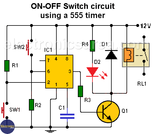
This ON-OFF switch circuit uses the well-known 555 timer. The timer activates a relay through a bipolar transistor in order to connect or disconnect the device we want to control.
Manual activation is performed through two momentary contact switches. Switch 1 (SW1) is used to enable the device, and Switch 2 (SW2) is used to disable it.
When the activation switch is pressed:
- The voltage on pin 2 of timer 555 changes sharply from 12 V to 0 volts. (triggers the 555). The timer output (pin 3) passes a nearby 12-volt voltage.
- The 12 volts, at the output of the 555, activates the relay through the transistor Q1 (the transistor enters the saturation region)
When the deactivation switch is pressed:
- To deactivate the relay (and disable the device we want to control), switch 2 (SW2) is pressed. When switch 2 is pressed, the voltage on pin 6 of the 555 timer changes temporarily to 12 volts.
- The output of the 555 (pin 3) will have a voltage close to 0 volts, the transistor will be in its cutoff region, and the relay will be disabled.
Suggested PCB for the on-off switch circuit
The next two diagrams show the proposed PCB for this circuit and an image of what would be the finished circuit.
On the last diagram, we see two connections made by the component side (blue). To see them well, you only need to expand a little of the diagram.
Note: The circuit works well in a range of 5 to 15 volts. You can use a 9-volt battery, so you have a portable circuit.
List of components for the circuit
- 2 3.3 MΩ resistors (R1, R2)
- 1 10 kΩ resistor (R3)
- 1 1 kΩ resistor (R4)
- 1 10-nF capacitor (C1)
- 1 2N2222 NPN transistor or similar (Q1)
- 1 1N4148 rectifier diode or similar (D1)
- 1 red LED (D2)
- 1 555 timer (IC1)
- 1 relay (same voltage of power supply) (RL1)
- 2 NO (normally open) switches (SW1, SW2)
- 3 2-pin terminal blocks. Switches (CN1, CN2), battery (CN3)
More timer Circuits
- Perfect Square Wave – Formula – Examples
- High current pulse generator
- Electronic Doorbell Circuit (555 & CD4017)
- Automatic Night Light (555 & relay)
- Sound Activated Flash trigger (555 & LM386)
- Off-Delay Timer Circuit using 555 IC
- Time Delay circuit using (Triac & 555 IC)
- 5 to 30-Minute Timer Circuit (7555 IC)
- Long Duration Timer with NOR gates
- Missing pulse detector circuit (555 timer)
- ON-OFF Switch circuit using a 555 IC (PCB)
- Event Sequencer using the 555 timer


the resistor of 3.3k ohm burnt I wonder why and I supplied it with a 12v 0.5 amps
Hello Phatty
I do not see a reason, why the resistor has burned. Check the circuit that you put together and try again. The resistor has a value of 3.3M.
regards
When the circuit is working on 9 vdc (SMPS) adapter, and another mains switches in the same room are operated the circuit automatically became ON ( i. e. without touching any part of the circuit).
What should I do?
Hi Vasudeo V Ajarekar
It seems to me that there is a peak voltage that causes the circuit to activate.
Place a 10 uF electrolytic capacitor between the terminals of the 9 volt source. I hope it works well.
regards.