Home / Operational Amplifiers / Window comparator using Operational Amplifiers
Window comparator using operational amplifiers
A window comparator using op-amps lets you know if a signal (voltage level) is within or outside a previously defined acceptable voltage limit. Using a comparator or an operational amplifier that controls the upper voltage level and another comparator that controls the lower voltage level, a window comparator can be implemented.
The voltage level to be reported (Vin) is applied to the inverting input of the op amp that controls the upper limit (Vh) and also to the non-inverting input of the op amp that controls the lower limit (VL).
By setting the upper limit voltage and lower limit voltage at terminals Vh and Vl, the range of voltages in which the window comparator output will be active is defined.
The LED will only light up when the outputs of the two op amps are at a low level, indicating that the Vin signal is within the range of allowable voltages. Then the first transistor will be in its cutoff region and function as an inverter, and the second transistor will enter its saturation region, turning on the LED.
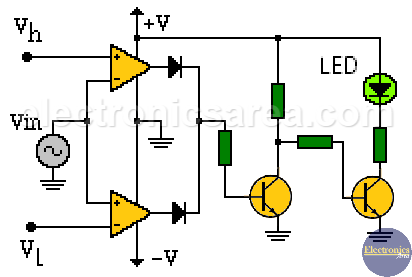
Window comparator using two comparators or two op-amps.
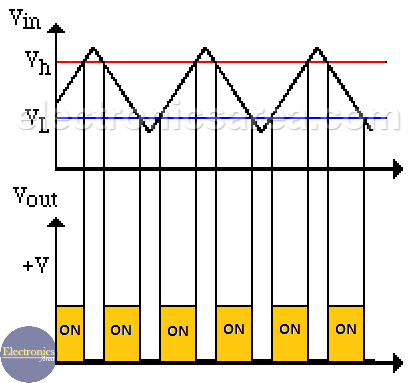
Window comparator input and output waveforms
From the two diagrams, it can be clearly seen that the LED lights up when the input signal (triangle wave) is below the upper limit (red line) and above the lower limit (blue line).
A high level at the output of either of the two operational amplifiers would activate the LED or alarm circuit (through a relay) that indicates that the signal is not within the range of voltages for which the comparator was designed.
More Op. Amp. Tutorials
- Op Amp Open Loop Gain – Op Amp Open Loop Configuration
- How to use op amps with a single rail power supply?
- Non-inverting Operational Amplifier
- Inverting Summing Amplifier using Op Amp
- Op Amp Voltage follower / Voltage Buffer
- Operational Amplifier as Comparator
- Window comparator using op amps

")

