Home / Circuits / Timer circuits /
Event Sequencer Using the 555 Timer
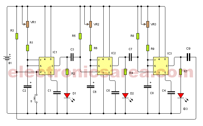
This event sequencing circuit uses several 555 timer to control an event sequence, where an event does not start if the previous event has not ended.
Some applications where this circuit can be applied are those that are similar to the simple operation of a washing machine, or those where you have to turn on and turn off several devices and the requirements are that for the current event to start, the previous event must have ended.
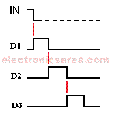
The diagram, where the control outputs are displayed as LEDs on, illustrates the operation of an event sequencer.
How the event sequencer using 555 timer works?
The design of the circuit is very simple and consists of a base circuit, which is repeated as many times as there are events. This base circuit consists of a 555 timer and its associated components, operating as a monostable multivibrator. There is also a small resistor and capacitor network, connecting the circuit stages (See R5 and C3, R8 and C7, R3 and C9)
Each time a timer finishes its operation, it triggers the next base circuit, via the RC network. This last one in turn triggers the next, and so on until the sequence of events is finished.
Each event has a duration time set by the resistor and capacitor combination of the respective timer. This way you may have different times for each event. The duration of each event depends on the event itself.
Output time duration for each timer can be varied from 1 second to 53 second, approximately. The time adjustment is made with the VR1, VR2, VR3, etc. potentiometers.
On this circuit diagram, the output of each timer activates a LED, but these outputs can be used to activate a device such as a relay. The number of timers that are needed depends on the number of events that the circuit must control. Circuit operation starts by activating a momentary NO contact switch on the first timer.
List of circuit components for the Event Sequencer
The number of circuit components depends on the number of events to be controlled. The following component list shows the parts for the circuit of a sequence of 3 events.
- 3 555 IC timers (IC1, IC2, IC3)
- 3 22K, 1/4 watt resistors (R1, R6, R9)
- 3 1K, 1/4 watt resistors (R2, R4, R7)
- 3 100K, 1/4 watt resistors (R3, R5, R8)
- 3 1M potentiometers (VR1, VR2, VR3) that allows to vary the monostable output time
- 3 47uF electrolytic capacitors (C2, C6, C8)
- 3 0.01uF capacitors (C1, C4, C5)
- 3 1uF capacitors (C3, C7, C9)
- 3 LEDs (D1, D2, D3)
- 1 NO momentary contact switch (S)
More timer Circuits
- Perfect Square Wave – Formula – Examples
- High current pulse generator
- Electronic Doorbell Circuit (555 & CD4017)
- Automatic Night Light (555 & relay)
- Sound Activated Flash trigger (555 & LM386)
- Off-Delay Timer Circuit using 555 IC
- Time Delay circuit using (Triac & 555 IC)
- 5 to 30-Minute Timer Circuit (7555 IC)
- Long Duration Timer with NOR gates
- Missing pulse detector circuit (555 timer)
- ON-OFF Switch circuit using a 555 IC (PCB)
- Event Sequencer using the 555 timer


