Home / Transformers /
Equivalent transformer circuits
Normally, in the designs and analysis where transformers are used, it is very common to use the characteristics of the transformer as if it were an ideal transformer.
This means that:
- It has no heat losses.
- No voltage drops in the windings.
- There are no capacitance due to the windings.
- There are no hysteresis losses in the core, etc.
The above is not always convenient, and sometimes it is necessary to take these parameters into account. Equivalent transformer circuits are used for this purpose.
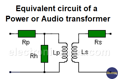
Equivalent circuit of a power or audio transformer
The values are:
Rp: is the resistance of the primary winding measured directly with a multimeter.
Rs: is the resistance of the secondary winding measured directly with a multimeter.
This means that:
Any voltage, which is in the primary winding, will appear in the modified secondary by a factor 1/n.
Any current, which is in the secondary winding, will appear in the modified secondary by a factor of n.
An impedance across Ls is reflected in Lp multiplied by a factor equal to 1/n2 (see ideal transformer).
Where n: is the transformation ratio or turns ratio between the primary and secondary windings.
The Rh resistance represents the hysteresis losses in the core. It is usually several times larger in magnitude than the XLp Reactance (primary winding reactance). Depending on its magnitude, it could be neglected.
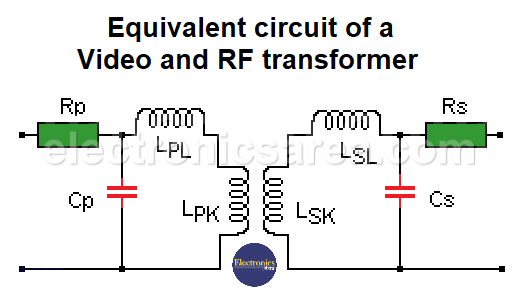
Equivalent circuit of a video and RF transformer
In this case, the skin effect is not negligible and causes the values of Rs and Rp to be larger than the direct measured values in the windings.
They are assumed to be transformers that do not have perfect magnetic coupling because they have air or ferrite cores. The subscript k indicates coupling and the subscript L indicates leakage in the reactances. Thus:
LP = LPL + LPk
LS = LSL + LSk
k = LPk / LP = LSk / LS
Values of k (coupling index) for air core transformers:
- k = 0.95 : when the winding of the windings are together (two wires wound together).
- k = 0.90: when the primary winding is on top of the secondary winding
- k = 0.35: when the windings are one after the other and their length is equal to half of the diameter
- k = 0.10: when the windings are one after the other and their length is equal to 2 diameters.
- CP and CS represent the capacitance of the windings, ranging from 0.01 to 0.02 pF per turn.
More Transformer Tutorials
- Ideal Transformer Working Principle
- Transformer Turn Ratio (K)
- Impedance matching Transformer
- Autotransformer
- Transformer Structure
- Power Transformer usage
- Equivalent transformer circuits (power, audio, video and RF)
- Why is the core of a transformer laminated?


