Home / Transformers /
What is an ideal transformer?
The ideal transformer is an electromagnetic device that allows AC voltage and current to be increased or decreased while maintaining constant power. (The power at the output of the ideal transformer is equal to the power at the input).
Power ratio between primary and secondary windings
As a result of the voltage transformation, there is a transformation of the electric current (alternating current) between the input and the output of the transformer, in such a way that the power delivered by the transformer is equal to the power received.
For the ideal transformer: Output power = input power (Po = Pi).
So when a voltage increases, the electric current decreases by the same factor, maintaining equality. Look at the formula. If P = V x I, then Vi x Ii = Vo x Io.
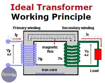
The transformer consists of an iron core with several sets of turns of wire wound around it. These sets of turns are the primary (P) and secondary (S).
How the ideal transformer works
- The primary winding receives a changing voltage at its inputs, causing a changing electric current to flow through it.
- The changing current induces a magnetic flux in the iron core.
- Since the secondary winding and the primary winding are wound on the same iron core, the same magnetic flux flows through them.
- The magnetic flux through the coils of the “secondary” will produce a changing voltage at its outputs.
- If a load is connected to the outputs of the secondary, a changing electric current will flow through it (for example, the secondary winding is connected to a load resistor).
Voltage Transformation Ratio
The output voltage of the transformer, Vs (the secondary), is scaled from the input voltage, Vp (the primary), by a factor equal to the ratio of the number of wire turns in their respective windings.
Vs/Vp = Ns/Np
The output voltage at the secondary winding is then given by Vs = (Ns/Np) x Vp.
Note that the output voltage, Vs, depends on the ratio of Ns (number of turns of the secondary winding) and Np (number of turns of the primary winding). Vs can be higher or lower than Vp.
Current Transformation Ratio
Like the voltage, the input current (Ip) is scaled from the output current (Is) by a factor equal to the number of turns of the wire in its respective winding.
Ip / Is = Ns / Np.
If we know the current in the secondary winding (Is), we can find the current in the primary winding (Ip) using the following formula: Ip = (Ns/Np) × Is.
More Transformer Tutorials
- Ideal Transformer Working Principle
- Transformer Turn Ratio (K)
- Impedance matching Transformer
- Autotransformer
- Transformer Structure
- Power Transformer usage
- Equivalent transformer circuits (power, audio, video and RF)
- Why is the core of a transformer laminated?
")


