Home / Capacitors /
Alternating current in capacitive circuits
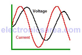
Unlike the behavior of a capacitor in direct current (DC), the alternating current (AC) passes more easily through a capacitor. Another feature of the alternating current flowing in a capacitor is that the voltage appearing at its terminals is 90° behind the electric current.
This phase difference between voltage and current is because the capacitor is opposed to abrupt changes in voltage across its terminals. Voltage and current are out of phase.
What does it mean to be out of phase?
It means that the maximum voltage value appears 90° after the maximum current value. The diagram shows that the red curve is always 90° (1/4 cycle) before the black curve. Then we say that the voltage is delayed with respect to current or what is the same, the current is ahead of the voltage.
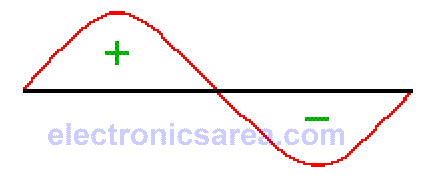
If the instantaneous values of current and voltage are multiplied, a sinusoidal wave with a frequency twice the frequency of the current or voltage is obtained. This is the waveform of the power. (remember that: P = I x V, Power = Current x Voltage.
This curve has a positive part and a negative part. This means that for some time the capacitor receives power and in another time, it delivers power.
The curve shows that the capacitor does not consume power. Ideally, the capacitor delivers the same power it receives. When an alternating voltage is applied to a capacitor, there is an opposition to the flow of alternating current.
The value of this opposition is called capacitive reactance (Xc) and can be calculated using the Ohm’s law: XC = V/I, and the formula: XC = 1/(2πfC), where:
- XC = capacitive reactance in ohms
- f = frequency in Hertz (Hz)
- C = capacitance in farads (F)
- π = 3.14159
The equivalent series resistance (ESR)
The capacitor discussed in the previous paragraph is ideal. The actual capacitor has a series resistance due to several factors like the metal plates, dielectric, etc.
The ESR is equivalent to the quality factor Q of the inductor. A small value of ESR is better.
More capacitor tutorials
- What is a Capacitor?
- Capacitors in series – Capacitors in parallel
- Capacitor in direct current (DC)
- Dielectric constant / Relative Permittivity
- Capacitor Charging Process
- Capacitor Discharging Process
- Capacitor in alternating current (AC)
- Impedance of a capacitor – Capacitive reactance of a capacitor
- Electrolytic capacitor


