Home / Capacitors /
Capacitor Charging Process
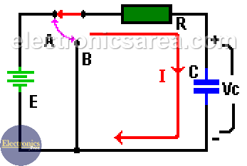
A capacitor is a device that, when connected to a DC power source, has an interesting behavior. See the diagram below.
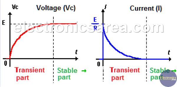
When the “A” switch is closed, the current “I” suddenly increases to its maximum value (such in a short circuit) and has the value I = E/R amps. Then it gradually decreases until the current has a value of 0 “zero” amps, as shown in the diagram below.
On the capacitor charging process, the voltage across the capacitor does not change instantly when it rises from 0 to E volts. E is the value of the DC voltage source connected in series with R and C. (See the diagram).
The time it takes the voltage on the capacitor (Vc) to go from 0 volts to 63.2% of the supply voltage (E) is specified by the formula: T = R x C, where:
- Resistor (R) is in ohms (Ω).
- Capacitor (C) is in millifarads (mF).
- Time (T) is in milliseconds. (mS).
After 5xT (5 times T) the voltage rises up to 99.3% of its final value. The value of T is called: “Time Constant”. Analyzing the two charts below, we can see that they are divided into:
- A transient part where the values of Ic and Vc varies with time. (Approximately 5 times the time constant T).
- A stable part where values of Vc and IC are constant.
Vc, Ic and VR values, at any time, can be obtained using the following formulas:
- Vc = E + (Vo – E) x e-t/T, where Vo is the initial voltage of the capacitor (in many cases this is 0 Volts).
- Ic = [(E – Vo) / R] x e-t/(T/R), where Vo is the initial voltage of the capacitor (in many cases this is 0 Volts).
- VR = E x e-t/T
where: T = R x C.
More capacitor tutorials
- What is a Capacitor?
- Capacitors in series – Capacitors in parallel
- Capacitor in direct current (DC)
- Dielectric constant / Relative Permittivity
- Capacitor Charging Process
- Capacitor Discharging Process
- Capacitor in alternating current (AC)
- Impedance of a capacitor – Capacitive reactance of a capacitor
- Electrolytic capacitor


