Home / Circuits / Timer circuits /
Missing pulse detector circuit using the 555 timer
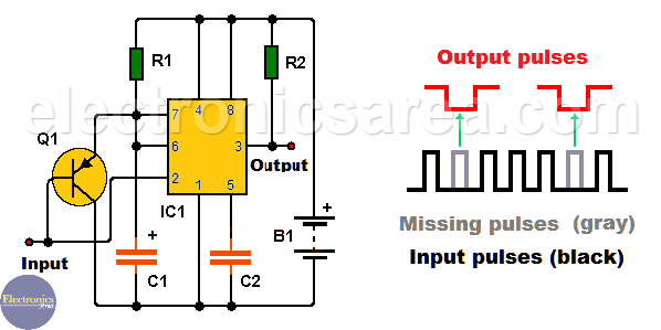
This missing pulse detector circuit or No pulse detector circuit is very interesting because it can detect or warn of the absence or delay of an expected pulse, which under normal conditions should be received at predefined time intervals.
Interesting applications for the Missing pulse detector circuit are: (among others)
- – Monitoring the heartbeat of a patient
- – Monitoring the rotational speed of a device. The circuit warns when the speed drops, etc.
How the missing pulse detector circuit work?
To implement this circuit, we use a 555 IC configured as an astable multivibrator. See the diagram. The output of the 555 timer remains high while the pulses applied to its input occur in the correct intervals of time. If a pulse fall behind, or it is absent, the output of the 555 IC goes low, detecting a problem.
The values of resistor R1 and capacitor C1 are chosen depending on the application you have. The values of R1 and C1 on this circuit were chosen to observe its operation when the input is activated manually.
Input pulses are detected by pin 2 of the 555 timer. At this same point we connect the base of a PNP transistor (Q1) in order to discharge the capacitor C1, each time the expected pulse appears, and thus start a new charging.
If the pulses arrive at pin 2 of the 555 integrated circuit on the correct intervals of time, the capacitor C1 is discharged before its voltage level reaches the level that causes the output of the 555 timer to go low.
Note: This missing pulse detector circuit do not detect:
- If pulses are closely spaced
- If the pulse frequency increases.
List of components for the Missing pulse detector circuit
- 1 555 Timer (IC1)
- 1 PNP transistor NTE159 or similar (Q1)
- 2 10K resistors (R1,R2)
- 1 47uF electrolytic capacitor (C1)
- 1 0.01uF capacitor (C2)
- 1 9 volts battery
More timer Circuits
- Perfect Square Wave – Formula – Examples
- High current pulse generator
- Electronic Doorbell Circuit (555 & CD4017)
- Automatic Night Light (555 & relay)
- Sound Activated Flash trigger (555 & LM386)
- Off-Delay Timer Circuit using 555 IC
- Time Delay circuit using (Triac & 555 IC)
- 5 to 30-Minute Timer Circuit (7555 IC)
- Long Duration Timer with NOR gates
- Missing pulse detector circuit (555 timer)
- ON-OFF Switch circuit using a 555 IC (PCB)
- Event Sequencer using the 555 timer


