Home / Circuits / Timer circuits /
Time Delay circuit using Triac and 555 timer
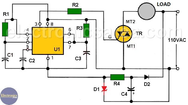
This Time delay circuit using Triac and 555 Timer is very useful when we want to activate or switch on, appliances or devices that work on alternating current (AC), after a preset time.
These appliances or devices can be: a washing machine, a refrigerator, a television set, a radio, a circuit that turns on a light temporarily, etc. Another options are to use a Variable timer circuit that also uses the 555 IC or the Light button with time delay.
The circuit uses the 555 integrated circuit on its monostable configuration. The timer triggers a TRIAC that works as a solid state relay and can control a load of up to 4 amps, when connected to 110 VAC.
Another circuit with time delay is the Light push button Time delay circuit
This circuit can be used in applications where two or more operations have to be performed in sequence. It can be used to delay the application of voltage to a fuel pump, a heating system, a fan, etc.
Time delay circuit operation
- Immediately after the circuit has been switched on, a trigger pulse is applied to the # 2 pin of the 555 timer, through the resistor – capacitor network R1 – C1
- The delay time is set by the resistance – capacitor network R3 – C3, which in this case is approximately 22 seconds.
Note: You can modify the delay time, changing the R3 and C3 values
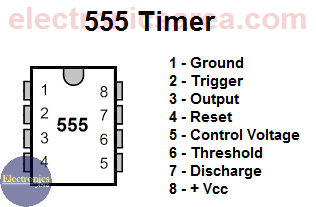
555 timer IC Pinout
After the delay time, the output of the timer 555 (pin 3) which is connected to the gate (G) of the TRIAC through the R2 resistor, powers on the load.
The 555 timer and its associated elements operate with 10 DC volts. This voltage is obtained using a transformerless voltage source implemented with a zener diode (D1), a resistor (R4), an electrolytic capacitor (C4) and a rectifier diode (D2.)
This network allows us to obtain 10 VDC directly from the 110 AC voltage without using the voluminous transformer.
Time delay circuit components
- 1 555 timer IC, Motorola MC1555 or similar (U1)
- 1 TRIAC, 2N6071 or similar (4 amps maximum) (TR)
- 1 10 volts / 5 watts Zener diode, 1N5347 or similar (D1)
- 1 rectifier diode, 1N4004 or similar (D2)
- 1 10K resistor (R1)
- 1 1K resistor (R2)
- 1 20M resistor (R3)
- 1 3.5K resistor (R4)
- 1 0.1uF capacitor (C1)
- 1 0.01uF capacitor (C2)
- 1 1 microfarad (uF) capacitor (C3)
- 1 10 uF / 250 V electrolytic capacitor (C4)
- 1 heatsink for TRIAC
")


