Temperature alarm circuit using a diode
The diagram below shows how a semiconductor diode is used as a temperature sensing element in a temperature alarm circuit using an operational amplifier.
Semiconductor diodes can be used as temperature sensors because they change their forward voltage as the temperature changes. The advantage of diodes is that their relationship between temperature and voltage is virtually linear.
How does the temperature alarm circuit using a diode work?
On this circuit the Zener diode is connected in series with the resistor R1, so that between the ends of the two voltage dividers formed by R2-R3 and R4-D1, there is a constant voltage of 5.6 V. Practically a constant current circulates for each of these dividers.
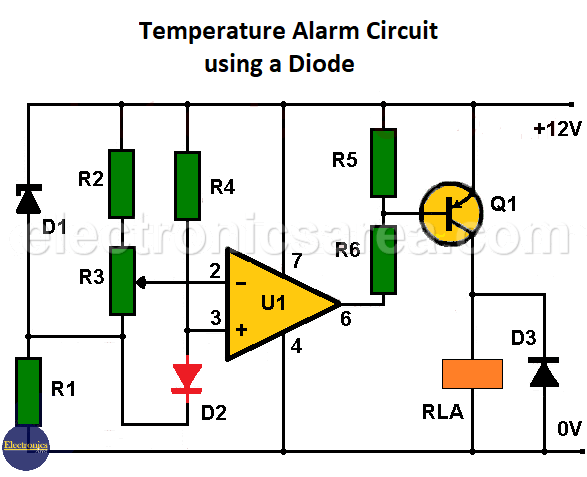
Temperature Alarm Circuit using a diode
So we have
- A constant reference voltage between the junction of the R2 and R3 resistors and the #2 pin of the op amp, and
- A temperature dependent voltage with a coefficient of -2 mV /°C between the junction of the R1 – R3 resistors and the #3 pin of the op amp.
A differential voltage with a coefficient of -2 mV/°C appears between pins 2 and 3 of the amplifier. To tune this circuit, diode D2 is raised to the desired temperature level and potentiometer R3 is slowly turned just before the relay is energized.
At this point, a differential voltage of 1 mV appears between pins 2 and 3 of the op amp, with the voltage at pin 3 below the voltage at pin 2, activating transistor Q1 and the relay.
When the temperature drops below the trigger level, the voltage on pin 3 rises above the voltage on pin 1 by approximately 2 mV/°C. Transistor Q1 and the relay are de-energized.
The circuit has a typical sensitivity of 0.5°C and can be used as an over-temperature alarm operating from below zero (0°C) to above the boiling point of water (100°C).
The operation of the circuit can be reversed to act as a low temperature alarm by reversing the pin 2 and pin 3 connections of the op amp.
Temperature Alarm Circuit component list
- 1 741 Operational Amplifier (U1)
- 1 2N3702 PNP Transistor (Q1)
- 1 5.6 V zener diode (D1)
- 2 common semiconductor diodes (D2, D3)
- 1 9V relay (RLA)
- 3 1.2 k resistors (R1, R5, R6)
- 2 4.7 k resistors (R2, R4)
- 1 1 k potentiometer (R3)
See more schematics like this on the alarm projects main page.
Other temperature alarms you may like:
- Car Temperature Alarm using 741 & 555 ICs
- Over temperature alarm circuit using Thermostat
- Temperature alarm circuit with Op. Amp.
- Temperature Alarm u with thermostats
over-temperature-alarm-using-operational-amplifier


