What is an RC High Pass Filter?
An RC high pass filter ( (passive high pass filter)) is a circuit made by a resistor and a capacitor connected in series, as shown in the image below.
The RC low pass filter allows only the passage of frequencies above a particular frequency called cut-off frequency (Fc) and eliminates frequencies below this frequency. These RC high pass filters are not perfect, so two analyzes are done.
Ideal RC High Pass Filter
An analysis with an ideal filter and another with a real filter. The unit of frequency is: Hertz or cycles per second.
The ideal RC high pass filter is a circuit made by a resistor and a capacitor in series, which allows the passage of frequencies above the cut-off frequency (Fc) and eliminates those that are below it.
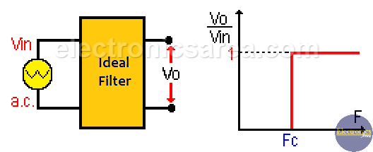
See in the previous image, that the frequencies that pass through the filter are those that are on the right side of the vertical red line, which represents the cutoff frequency.
Real RC High Pass Filter
The capacitive reactance (XC) changes with frequency. For high frequencies (above the cut-off frequency) the capacitive reactance XC is low, and the signals of these frequencies are not attenuated.
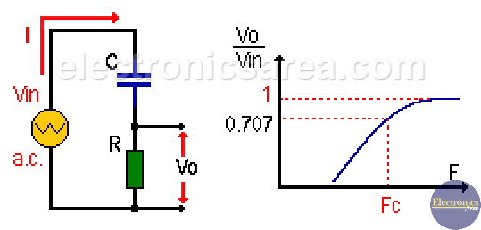
In contrast, for low frequencies (below the cut-off frequency) the capacitive reactance is large, so that these frequencies are affected by the filter.
Using Ohm’s law: Vo = I x R
Since Vin = I x Z = I x (R2 + Xc2)1/2, then: Vo = Vin [2πfRC / (1 + (2πfRC)2)1/2].
Where:
- Z = Impedance = (R2 + Xc2) 1/2
- Xc = capacitive reactance = 1 / 2πfC
- f = frequency
- R = resistor value (resistance)
- C = capacitor value
- π = Pi = 3.1416
The cut-off frequency is the frequency where the amplitude of the incoming signal falls to 70.7% (0.707) of its maximum value. This happens when XC = R. (capacitive reactance = resistance). If XC = R, the cut-off frequency is: Fc = 1/(2*π*R*C).
The frequency band above the cut-off frequency (Fc) is called the Pass Band, and the frequency band below Fc is called the Stop Band.
Phase angle of an RC low pass filter
The phase angle of an RC high pass filter as a function of frequency is obtained using the formula: ψ = tan-1 (R/XC).
Note: ( )1/2 = square root.
More Filters Tutorials
- Electronic filters – (low-pass, high pass, band pass
- RC Low Pass filter (passive low pass filter)
- RC High Pass filter (passive high pass filter)


