Home / Circuits / Timer circuits /
Electronic Doorbell Circuit using a 555 timer and a CD4017 decade counter
A very useful electronic doorbell circuit, to have between the circuits that send a warning or an alarm signal, which allows us to know that there is someone in front of our door.
This electronic circuit gives us all the possibility to change the tone of each of the 10 musical notes that the circuit has. This means we can create our own sound sequence.
The circuit consists of a 555 timer, a CD4017 decade counter, a UJT (UniJuntion Transistor), and a bipolar transistor.
How the Electronic Doorbell Circuit works?
The 555 timer is set up as an astable multivibrator. The UJT is used for the relaxation oscillator. To jump from one note to the next we use the CD4017 and to drive the speaker we use a NPN transistor.
This doorbell circuit generates ten notes, which can be modified with 10 potentiometers, varying the frequency at which the UJT oscillates.
The relaxation oscillator having a frequency which depends on the values of the C2 capacitor and the R14 resistor plus the value of the corresponding potentiometer connected to each of the outputs of the CD4017.
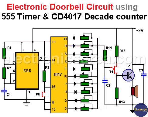
The astable multivibrator’s output (pin 3) sends a square waveform signal to the clock input of the decade counter (pin 14).
When we press the PB button, pin 15 of the CD4017 changes from 9 volts to 0 volts, thus the clock input (pin 14) of the CD4017 is enabled.
As long as the chime button is pressed, the CD4017 sequentially puts a high voltage pulse on its outputs. (see diagram).
-

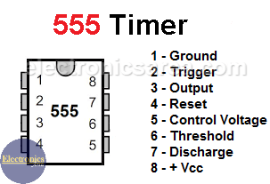
- 555 timer Pinout
-

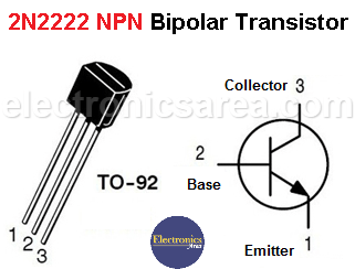
- 2n2222 BJT Pinout
Each output of the CD4017, enables the UJT relaxation oscillator with a different value of “R” (R = R14 + potentiometer). As the potentiometers values are modifiable, you can change the oscillation frequency for each 4017 output.
It is even possible to create gaps of silence by preventing one or more outputs of the 4017 from connecting to the oscillator.
The relaxation oscillator output, taken from the junction of the resistor R13 and the UJT, is applied to the base of the bipolar transistor that drives the speaker.
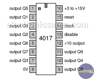
4017 Decade counter pinout
To change the cadence of the sound of the 10 notes, we can change the output frequency of the 555 timer. This is achieved modifying the values of resistor R2 and capacitor C1.
Circuit component list
- 1 555 timer IC (IC1)
- 1 CD4017 decade counter IC (IC2)
- 1 470 K resistor (R1)
- 1 220 K resistor (R2)
- 1 15 K resistor (R3)
- 1 10 K resistor (R14)
- 1 150 ohms resistor (R13)
- 1 220 ohms resistor (R15)
- 10 100 K potentiometer
- 10 1N4148 or 1N914 diodes
- 1 1uF / 250V capacitor (C1)
- 1 47nF / 250V capacitor (C2)
- 1 100uF / 12V capacitor (C3)
- 1 2N2646 Unijunction Transistor (UJT) (T1)
- 1 2N2222 NPN bipolar transistor (T2)
- 1 Normally Open (NO) contact button (PB)
- 1 8 ohms miniature speaker
You may be interested in:
- A doorbell circuit for the deaf, you can see Doorbell for Deaf People.
- Monitor the opening of one or more doors in the house, check Open door indicator.
- Check the refrigerator door opening and notify you if it has been left open, check Refrigerator door alarm circuit.
More timer Circuits
- Perfect Square Wave – Formula – Examples
- High current pulse generator
- Electronic Doorbell Circuit (555 & CD4017)
- Automatic Night Light (555 & relay)
- Sound Activated Flash trigger (555 & LM386)
- Off-Delay Timer Circuit using 555 IC
- Time Delay circuit using (Triac & 555 IC)
- 5 to 30-Minute Timer Circuit (7555 IC)
- Long Duration Timer with NOR gates
- Missing pulse detector circuit (555 timer)
- ON-OFF Switch circuit using a 555 IC (PCB)
- Event Sequencer using the 555 timer


