Motorcycle alarm circuit transistors and relay
All motorcycle owners want an alarm for their motorcycle. It would be a shame if you go looking for your bike and can’t find it where you left it. I hope this simple motorcycle alarm circuit helps you.
This motorcycle alarm has, as its main elements, three transistors, a relay and various sensors, including motion sensors.
The alarm can activate a small siren or the motorcycle horn, conveniently hidden to prevent it from being disconnected. The alarm is activated, when someone tries to unlock the motorcycle’s rudder or when someone moves it.
A normally open (NO) contact switch is attached to the motorcycle helm, and one or two motion sensors (mercury sensors) are placed in protected locations on the motorcycle.
When a sensor closes, the alarm sounds immediately. The sound continues for a preset time and stops. The alarm is then ready to be activated again.
The alarm has a main switch that is set in parallel with the motorcycle’s ignition key. In this way, the alarm is activated when we stop using the motorcycle and deactivated when we use it.
Operation of the motorcycle alarm circuit.
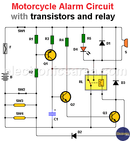
When a sensor closes, transistor Q1 saturates, causing capacitor C1 to charge.
When the voltage across capacitor C1 reaches 1.7 V, transistors Q2 and Q3, which are in Darlington configuration, conduct and activate the relay which in turn activates the siren.
If the sensor that was triggered is still closed, the alarm will continue to sound. If the sensor activation was momentary, the siren will sound for a predetermined time, and then it will be ready to reactivate.
The time the siren sounds depends on the values of R2 and C1. By varying these values, we vary the time the siren is active.
Circuit component list
- 1 BC557 PNP transistor (Q1)
- 2 BC547B NPN transistors (Q2, Q3)
- 1 12V single contact relay (RL1)
- 3 1K resistors (R1, R3, R5)
- 1 4.7K resistor (R2)
- 1 470 uF (microfarads) electrolytic capacitor (C1)
- 1 1 amp fuse (F1)
- 1 red LED (D4)
- 3 semiconductor diodes (D1, D2, D3)
- 1 12 volt siren
- 1 or 2 mercury sensors (Sw3, Sw4)
- 1 main switch (Sw1)
- 1 normally open (NO) alarm sensor (Sw2)
- B represents the motorcycle battery
You may be interested in Bike Flashing LED Lights Circuit


")
