Home / Semiconductors /
PUT – Programmable Unijunction Transistor
Characteristics of PUT
PUT is not a UJT (junction transistor). This transistor is a device that, unlike the common bipolar transistor, which has 3 layers, NPN or PNP, has 4 layers. It has 3 terminals like other transistors and are called: K (cathode), A (anode), G (gate).
Unlike the UJT, this transistor allows to control the RBB and VP values that are fixed in the UJT. PUT conduction parameters are controlled by terminal G.
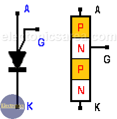
PUT Symbol and construction
Programmable Unijunction Transistor has two states:
- A conduction state (there is current between A and K and the voltage drop is small)
- A cut-off state when the current from A (anode) to K (cathode) is very small.
This transistor is polarized in the following way:
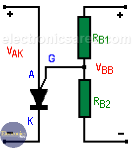
PUT polarization
When IG = 0,
VG = VBB * [RB2 / (RB1 + RB2)]
VG = n x VBB
where: n = RB2 / (RB1 + RB2)
The main difference between the UJT and these transistors is that the RB1 and RB2 resistors are internal resistors in the UJT, while in the PUT these resistors are on the outside and can be modified.
Although both transistors are similar, the Ip is weaker than in the UJT and the minimum operating voltage is lower in the PUT.
Programmable Unijunction Transistor Operation
To enter the active mode from the cut-off state (where the current between A and K is very small), the voltage between A and K must be raised to the value Vp, which depends on the value of the voltage at gate G.
Only until the voltage at “A” reaches the value Vp, this transistor will turn on and remain in this state until “Ia” (current through the transistor) has decreased in value.
This is accomplished by reducing the voltage between A and K or by reducing the voltage between “G” and “K”.
Operation of an oscillator using a PUT
The operation is:
Capacitor C is charged across resistor R until the voltage at “A” reaches the voltage Vp.
At this time, the transistor is activated and begins to conduct.
Voltage in VG drops to almost 0 (zero) volts and transistor turns off,
This process is repeated continuously (oscillation).
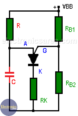
Basic oscillator circuit using PUT
Waveforms of the voltages at C, K and G are shown below.
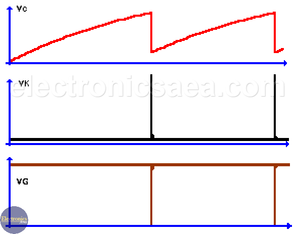
Oscillator Waveforms
The oscillation frequency is given by the formula: f = 1 / (1.2 x RC).


