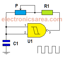
Pulse generator using NAND gate
This simple pulse generator using NAND gate is very useful and can be used as clock generator for other circuits. The circuit’s main element is a 2 input (Schmitt Trigger) NAND gate connected as NOT gate.
Analyzing the circuit diagram and remembering the truth table for a NAND gate, we know that when the two inputs are logic “1”, the output will be at logic “0” and when the two inputs are at “0”, the output will be a logical “1”.
Exactly the same behavior that would have a NOT gate.
How the pulse generator using NAND gate works?
The NAND gate has at its output a square wave whose frequency depends on the values of capacitor C1 and the series combination of the potentiometer P and resistor R1.
When the output of NAND gate is High (logical 1), the capacitor C1 (which has no charge) sends a logical zero (0) at the inputs of the NAND gate. The capacitor begins to charge through the resistor and potentiometer assembly.
Once the capacitor is charged, both inputs of the gate are high (logical 1), causing its output to go low (logic zero). With the low output, capacitor discharge begins through the same set of resistor and potentiometer in series, returning to its original state. The process is repeated continuously.
You can use a 3.0V to 15V power supply.
List of components for the pulse generator using NAND gate
- 1 CD4093: Quad 2-Input NAND Schmitt Trigger (U1). We only use 1 gate, of 4 available.
- 1 x 1 Megohm potentiometer (P)
- 1 x 10K resistor (R1)
- 1 x 47 uF capacitor (C1)


