What is the Mesh current method
The mesh current method is very useful to know all the current in a network of resistors. This method, a little more extended, is also applied to circuits where there are resistances and reactances.
Using the mesh current method, resistors current values are calculated, then it is easy to obtain their voltages and their consumed power. This method is based on Kirchhoff’s voltage Law.
The Mesh-Current Method or Loop Current Method is a technique used to find the currents circulating around a mesh with in any closed path of a circuit.
Steps to follow to make analysis by the mesh current method:
- Draw the circuit to be analyzed so that there is no one connection crossing over another. (if possible)
- Convert current sources into voltage sources.
- Draw the direction of the currents in the sense of the needles of the clock. The currents are called I1, I2, I3, … .etc. See example at the end.
- Make a table with the equations obtained from the circuit (Kirchhoff’s law of voltages). The number of rows in the table is the same as the number of currents established in step 3.
- Columns with unknown variables are placed on the left side of the equal sign, and the column with the constant values on the right side.
You may also want to read the Nodal analysis method
Example of Mesh Current Method
In order to obtain the values of the currents in the following circuit, the following steps are to be followed.
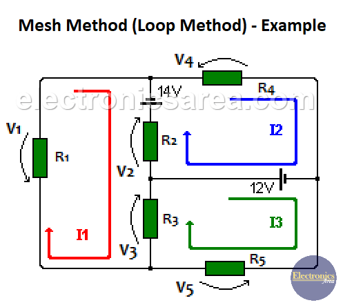
- Current I1 (red), I2 (blue), and I3 (green) meshes are established.
- For the I1 mesh: V1 + V2 + V3 – 14V = 0 (1)
- For the I2 mesh: -V2 + 14V + V4 – 12V = 0 (2)
- For the I3 mesh: -V3 -12V + V5 = 0 (3)
Note: When the voltage and current across a resistor are in the same direction, the voltage is considered negative. See voltage V2 on current loop I2 and voltage V3 on current loop I3.
If we replace the corresponding voltage values (with Kirchhoff’s law), we get the following:
- V1 = I1 x R1
- V2 = (I1-I2) x R2
- V3 = (I1-I3) x R3
- V4 = I2 x R4
- V5 = I3 x R5
If we replace the previous voltage values in formulas (1), (2) and (3), we obtain:
- For the I1 loop: I1 x R1 + (I1-I2) x R2 + (I1-I3) x R3 – 14V = 0
- For the I2 loop: – (I1-I2) x R2 + 14V + I2 x R4 – 12V = 0
- For the I3 loop: – (I1-I3) x R3 -12V + I3 x R5 = 0
The following values of the resistors are used: R1 = 10 ohms, R2 = 6 ohms, R3 = 4 ohms, R4 = 8 ohms, R5 = 2 ohms.
- For the I1 loop: 10I1 + 6 (I1-I2) + 4 (I1-I3) – 14V = 0
- For the I2 loop: -6 (I1-I2) + 14V + 8I2 – 12V = 0
- For the I3 loop: -4 (I1-I3) – 12V + 2I3 = 0
Rearranging the equations, we obtain:
For the I1 loop:
(10 + 6 + 4) I1 – 6I2 – 4I3 -14V = 0
20I1 – 6I2 – 4I3 = 14
For the I2 loop:
6I2 + 8I2 – 6I1 + 14V – 12V = 0
6I2 + 8I2 – 6I1 = -2
For the I3 loop:
4I3 + 2I3 – 4I1 = -12
The final equations are (as specified in step 4)
20I1 – 6I2 – 4I3 = 14
– 6I1 + 14I2 + 0I3 = -2
– 4I1 + 0I2 + 6I3 = 12
Since there are three unknown values (I1, I2, I3), there are three rows in the table. Using the substitution method or the determinant method, the following values are obtained:
I1 = 0.348 amps
I2 = 0.006285 amps
I3 = -1.768 amps. The minus sign indicates that the direction of the current I3 is in the opposite direction to the one assumed at the beginning.


