How to test diodes and how to test transistors
How to test diodes?
It is very important for an electronics technician to be able to determine if a diode is working well or not, because it allows him to make electronic devices work properly. However, not only technicians need to know this.
For an electronics hobbyist, who is implementing a circuit or checking an electronic project, it is very important to know if there is any problem with the electronic components he is using.
There are digital multimeters (VOM) that test a diode very easily, because it already comes with this option from the factory.
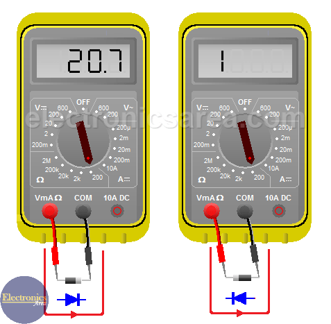
I’ll show you a typical method to test diodes with an analog VOM (it also works with a digital multimeter). First, the selector must be positioned to measure resistance (ohms), regardless of the scale. We do the following test on the picture above.
- Join the red lead probe with the anode of the diode (the non-striped side) and the black lead probe with the cathode (the striped side). The VOM will inject a continuous current to the diode. If the VOM shows low resistance, it means that the diode is forward-biased and it is working fine. If this resistance is very high, it may be a sign that it is an open diode and it has to be replaced.
- Join the red probe lead with the cathode and the black one with the anode. As in the previous case, we want to have a current flowing through the diode, but now in the opposite direction (from cathode to anode). If the reading shows a very high resistance, then the diode behaves as expected because it is reverse biased and there is almost no current flow. If the readings show a very low resistance, this could mean that the diode is in “short” and it has to be replaced.
Notes:
- The red probe should be connected to the terminal of the same color in the multimeter.
- The black probe should be connected to the terminal of the same color in the multimeter (common).
How to test transistors
To test transistors, the equivalent circuit of the NPN and PNP bipolar transistors is used. This equivalent circuit is composed of two diodes, and we follow the same technique we used to test a common diode.
The testing is performed between the base terminal (B) and the E and C terminals of the transistor. The NPN and PNP transistors have opposite methods.
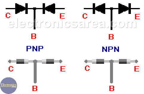
As in the common diode, if one of these “diodes” (the equivalent transistor “diodes”) does not work as expected, we have to change the transistor.
Note: Although this method is very reliable (99% in all cases), there are some cases where this is not met due to the characteristics of the transistor or diode. It is suggested to take it as 100% reliable for practical purposes.
More Instruments & Measurements Tutorials
- Multimeter - VOM - Tester
- Measuring resistance with an analog multimeter
- Low resistance measurement
- Measuring the resistance of sensitive components
- What is a Wheatstone bridge circuit?
- How to extend analog multimeter voltage range?
- Testing diodes and transistors with a multimeter
- What is a logic probe?
- Scientific Notation - Engineering Notation
- kWh - cost of electrical energy
- DIY circuit diagrams for test equipment


