Home / Semiconductors /
Increasing the Output Voltage of 78XX Regulators
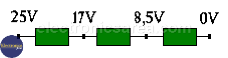
Remember that when we connect a group of resistors in series, each one causes a voltage drop that is proportional to the value of the resistor. Assuming the resistors are equal, the voltage drop across each resistor will be equal.
The voltage regulator IC is like a power supply stabilized by a Zener diode. This diode is placed between the “Adj” pin of the IC and ground.
How to increase the output voltage of 78XX regulators?
To increase the output voltage of 78XX regulators, we place a zener diode or resistor between the “Adj” input and ground. Let us make a practical assumption. Let’s look at the following circuit.
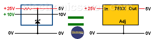
In the figure above (left side) we see a power supply stabilized by a Zener diode. To understand the assumption, we have considered a circuit in which there is a common line (0 V) and two positive lines of +10 V and +25 V.
If we place the 5V zener diode between the +25V and 0V lines, as shown in the figure, we get +5V and +10V outputs. The equivalent circuit with a voltage regulator is shown in the picture above (right side).
If we place the 5V zener diode between the 10V and 0V lines, we get +25V and +5V at the output. The equivalent circuit with a voltage regulator is shown in the figure below.
The diagram of this circuit and its equivalent with an integrated regulator can be seen in the following figure.
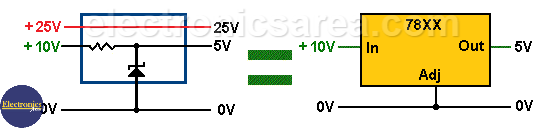
Assuming the diode is placed between the 25 V and 10 V lines, the diode will stabilize the voltage between these two lines at 5 V.
In this case, the outputs we obtain will be +10 V, since we have not touched this line, and +15 V, which is the sum of the 10 V of the previous line and the 5 V that the zener diode has stabilized between the two positive lines.
So we have created a dummy 10V line (in the example above); then the output will be 10V + 5V = 15V.
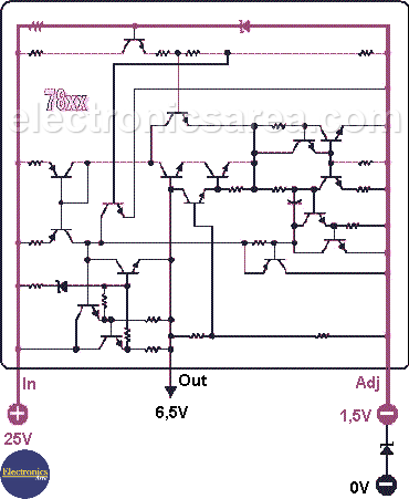
Assuming that instead of a resistor we put a 1.5V zener diode between the IC’s “Adj” pin and ground (0V), the output will be +5V +1.5V = +6.5V. 5V is the output of the voltage regulator and 1.5V is the voltage across the diode.
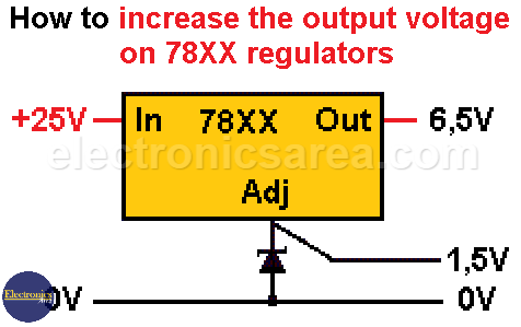
How to increase the output voltage of 78XX regulators
Assuming that instead of a resistor we put a 1.5V zener diode between the IC’s “Adj” pin and ground (0V), the output will be +5V +1.5V = +6.5V. 5V is the output of the voltage regulator and 1.5V is the voltage across the diode.
Finally, we will see the voltage regulator diagram provided by Texas Instruments.
Author: Luis González López. lgonzalez_280@hotmail.com. Spain.


