Fridge door alarm circuit (LDR, 555)
This fridge door alarm circuit alerts you when the door has been left open. Very important, because the power consumption increases significantly when this happens.
How the fridge door alarm circuit works?
Note: LDR = Light Dependent Resistor = Photoresistor
This alarm project uses an LDR or photoresistor as door sensor. When the sensor is illuminated by the light within the refrigerator, the circuit will emit an intermittent sound to attract attention. When the door is closed, the light goes off and the circuit will stop emitting the sound.
The refrigerator door alarm circuit uses two 555 timers, connected as shown on the diagram.
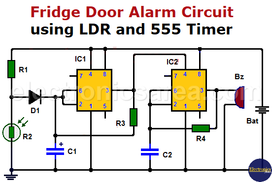
- When the LDR is not illuminated (the door is closed), the voltage on pin 2 (trigger) of the first 555 timer, is high and the voltage of the output (pin 3) is low. This causes that the second 555 timer remains disabled (low voltage level on pin 4) and no alarm sound.
- When the LDR is illuminated (the door is open), the voltage level on pin 2 of the first 555 timer goes low and its output (pin 3) begins to oscillate (square wave).
When the voltage level of the first 555 output (pin 3) is on high level, it enables the second 555 timer, which oscillate like the first 555 timer, but at a higher frequency. The output of the second 555 timer is connected to a buzzer (Bz) that will beep.
The circuit uses a 9 volt battery, and should be placed as close as possible to the inner light of the refrigerator. The circuit must be sealed in a waterproof box to prevent moisture from affecting its operation.

LDR (Light Dependent Resistor) – Photoresistor
List of components for the Fridge door alarm circuit
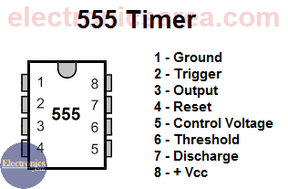
- 2 x 555 timers (IC1, IC2)
- 1 x 1uF (microfarad), 25V electrolytic capacitor (C1)
- 1 x 100nF (nanofarad) capacitor (C2)
- 1 x 10K, 1/4W resistor (R1)
- 1 x LDR (R2)
- 1 x 2.2M, 1/4W resistor (R3)
- 1 x 1M, 1/4W resistor (R4)
- 1 x 1N4148, semiconductor diode or similar (D1)
- 1 x 9 volts Buzzer (z)
You may also like Door opening monitor circuit


There is no battery on this diagram.
Hello Vladimir
Thank you for showing us the error in the diagram. The 9 volts battery is connected as follows:
– The positive battery terminal is connected to the top of the R1 resistor
– The negative battery terminal is connected to ground
regards