Home / Operational Amplifiers / Inverting Summing Amplifier using Op Amp
What is an Inverting Summing Amplifier?
The inverting summing amplifier with op amp has an output voltage equal to the sum of the voltages it has at its inputs. The following explanation is based on an adder of three inputs, but applies to an adder of any number of inputs.
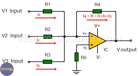
Each of the inputs has a resistor (R1, R2, R3), called input resistor which, combined with the feedback resistor (Rf = R4), form an inverting summing amplifier with a gain obtained using the formula:
Av = – (Feedback resistance) / (input resistance) = – Rf/Rin, where
- Rin = R1, R2, R3
- Rf = R4
This formula applies to all inputs.
DC summing inverting amplifier
From the above diagram, it can be seen that input currents are:
- I1 = (V1 – Vx) / R1
- I2 = (V2 – Vx) / R2
- I3 = (V3 – Vx) / R3
In an inverting amplifier, the current of the input signal flows through the feedback resistor. This is so due to the “virtual ground” characteristic of the operational amplifier, where the two inputs, Vx and Vy of the operational amplifier are equal to 0. (Vx = Vy = 0).
So:
- I1 = V1 / R1
- I2 = V2 / R2
- I3 = V3 / R3
Since there are three input currents in this summing amplifier, then all these currents will flow through the feedback resistor. Thus, the total current in the feedback resistor is equal to the sum of the input currents. The feedback current is equal to: It = I1 + I2 + I3.
Using the previous current formulas, we obtain the total input current:
- It = Vout / R4
- It = I1 + I2 + I3
Using the above formulas, we find that the output voltage is:
Vout / R4 = V1 / R1 + V2 / R2 + V3 / R3
Vout = – (V1 x R4 / R1 + V2 x R4 / R2 + V3 x R4 / R3)
If R1 = R2 = R3 = R4, then: Vout = – (V1 + V2 + V3)
AC Inverting Summing Amplifier
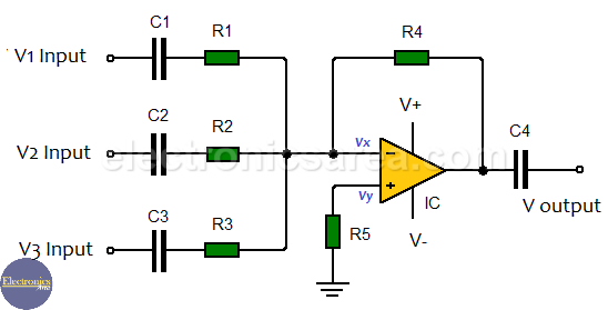
The summing amplifiers work both in direct current (DC) and in alternating current (AC). In order to work in alternating current, coupling capacitors are placed at the inputs and output of the amplifier.
The function of the coupling capacitors in the summing amplifier in alternating current is to block the DC component of the input and output signals, allowing only the alternating component to pass.
More Op. Amp. Tutorials
- Op Amp Open Loop Gain – Op Amp Open Loop Configuration
- How to use op amps with a single rail power supply?
- Non-inverting Operational Amplifier
- Inverting Summing Amplifier using Op Amp
- Op Amp Voltage follower / Voltage Buffer
- Operational Amplifier as Comparator
- Window comparator using op amps


