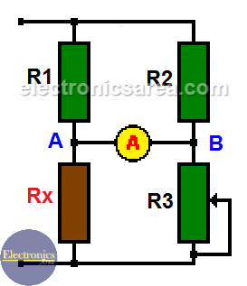
The Wheatstone bridge circuit
The Wheatstone bridge circuit is a very interesting circuit, and it is used to measure the value of passive components such as resistors. The circuit can be connected to any direct current voltage (VDC), but it is not recommended to use it over 12 volts.
The Wheatstone bridge circuit was designed in 1833 by Samuel Hunter Christie (1784-1865). However, It was Mr. Charles Wheatstone who gave many uses to the Wheatstone bridge circuit when he discovered it in 1843. As a result, this circuit bears his name. It is the most sensitive circuit to measure a resistance.
When the bridge is in balance: R1 = R2 and Rx = R3, then…. R1/Rx = R2/R3.
In this case, the voltage between points A and B (where we placed the ammeter) is 0 volts. This shows us that there is no current flowing between these two points (0 amps).
When Rx = R3, VAB = 0 volts and there is no current on the ammeter (A).
If the value of Rx is not known, the bridge must be balanced by modifying the value of R3. When equilibrium has been achieved, Rx will be equal to R3 (Rx = R3). R3 must be a variable resistor with a dial to obtain very precise values.
For example:
If R1 and R2 = 1 KΩ (Kilohm) and R3 = 5 KΩ, Rx must be 5 KΩ to make the voltage between A and B (VAB) = 0 volts (there is no current through the ammeter).
Therefore, you only have to connect the unknown resistor (Rx) to the circuit and start to vary the value of R3 until the current between A and B is zero. When this happens, the value of RX will be equal to the value of R3.
Some applications of the Wheatstone bridge circuit in the industry are temperature sensors, pressure sensors, etc. (they are devices that vary the value of their resistance according to the variation of the mentioned variables).
It is also used in power distribution systems, where it is used to detect breaks or faults in the distribution lines.
It is in the ammeter that you can see the level or degree of imbalance or difference between the normal value to be measured and the actual measurement.
More Instruments & Measurements Tutorials
- Multimeter - VOM - Tester
- Measuring resistance with an analog multimeter
- Low resistance measurement
- Measuring the resistance of sensitive components
- What is a Wheatstone bridge circuit?
- How to extend analog multimeter voltage range?
- Testing diodes and transistors with a multimeter
- What is a logic probe?
- Scientific Notation - Engineering Notation
- kWh - cost of electrical energy
- DIY circuit diagrams for test equipment


