Home / Power Supplies /
Unregulated Power Supplies
Simple power supplies are built with a transformer, a rectifier (diodes or bridge rectifier), and a filter (capacitor). These sources do not have voltage regulators and are called unregulated power supplies.
Unregulated sources do not provide sufficient quality because their output voltages change with the current flowing through the load and with possible changes in line voltage.
In addition, a significant amount of ripple occurs at the network frequency. Therefore, they are generally not suitable for most applications.
Regulated Power Supplies
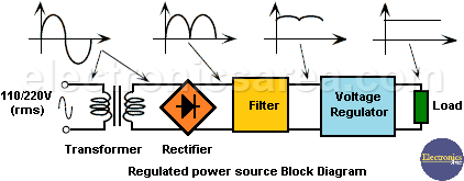
The following figure presents a typical block diagram of a regulated power supply. The input from the mains (110-220 V, 50-60 Hz) is applied to a transformer in order to reduce its amplitude.
A diode rectifier rectifies the signal, which is filtered (usually through a capacitor) to produce an unregulated DC output. The voltage regulator provides a much more regulated and stable output to power a load.
The function of the voltage regulator is to provide a stable and well specified voltage to power other circuits from a poor quality input power source.
In addition, they must be able to provide output currents from a few tens of milliamps, in the case of small regulators, up to several amps, for large regulators.
Voltage regulators are classified as:
Series or linear voltage regulators
These regulators control the output voltage by continuously adjusting the voltage drop across a power transistor connected in series between the unregulated input and the load. Since the transistor must conduct current continuously, it operates in its active or linear region.
Although they are simpler to use than switching regulators, they tend to be very inefficient due to the power consumed by the series element. Their efficiency is around 20%, and they are only effective for low power (<5 W).
Switching regulators
These regulators use a power transistor as a high-frequency switch, such that energy is transferred from the input to the load in discrete packets. The intensity pulses are then converted to direct current by means of an inductive and capacitive filter.
Since the transistor operates as a switch, it consumes less power than when operating in its linear region. These regulators are more efficient (up to 80%) than the linear ones; in addition, they are smaller and lighter.
These regulators can be designed to operate directly on rectified and filtered mains voltage, eliminating the need for bulky transformers. The disadvantages that these regulators are greater complexity of the circuit and greater ripple noise.
Switching regulators are used especially in digital systems, where high efficiency and low weight are often much more important than small output ripple.
The current trend in multi-output power supply design is to use switching regulators to take advantage of their benefits and then use series regulators to achieve cleaner and better regulated voltages.
After the operational amplifier, the voltage regulator is probably the most widely used integrated circuit.
You may be interested in: