Rain Alarm Circuit using 555 IC
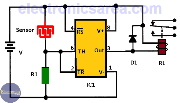
This Rain alarm circuit using 555 IC, uses the water property to conduct electricity. To implement the water sensor, we use two pieces of metal which are placed close enough for a drop of water to let current flow between the metal plates.
This sensor can be made, taking as a basic idea the sensor shown in the diagram. The distance between tracks should be as small as possible. A printed circuit with these characteristics can be manufactured.
To make sure that the water is detected when the rain starts to rain, a funnel can be used (this way it is possible to capture more water). The funnel must be out in the open and its outlet is placed just above the sensor. It is important to place the sensor in a place that dries easily once it has stopped raining.
Operation of the rain alarm circuit using 555 IC
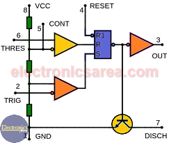
This circuit uses 555 timer as a level detector. The timer and it takes advantage that its activation voltage is greater than the deactivation voltage.
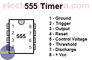
Remember that the TR input (trigger) is activated with a voltage of 1/3 of the supply voltage and that the TH input (threshold) with a voltage of 2/3 of the supply voltage. These voltages are two different reference voltages. See the following diagram.
This hysteresis feature prevents the relay from constantly activating and deactivating when a little rain is detected. A solid state relay would work without any problem.
Sometimes the water you want to detect is very pure, such as distilled water. This type of water does not conduct electricity well. In this case, you can change the R1 resistor value to 2.2 M or more. If, on the contrary, the circuit is activated very easily and produces false alarms, it is better to change the R1 resistor value to 220 ohms or fewer.
The D1 diode is used to protect the timer 555 from a reverse polarity voltage that occurs when the relay is deactivated.
The circuit can be powered with a voltage ranging from 5 to 15 volts.
List of components for the Rain alarm circuit
- 1 555 integrated circuit (IC1)
- 1 1N4001 diode (D1)
- 1 1 Megohm resistor (R1)
- 1 relay. Relay voltage have to be equal to or slightly lower than the supply voltage V. (200 mA) (RL)
- 1 rain sensor (made as shown in the diagram)