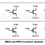
Electronics Area

Electrical and Electronics Tutorials and Circuits
  • Home
  • Tutorials
    • DC Theory Tutorials
    • Alternating Current (AC)
    • Digital Electronics
  • Semiconductors
  • Circuit diagrams
    • Audio Circuits & Projects
    • Control Circuits
    • Detector Circuits and Projects
    • Power supply
    • Timer Circuits and Projects – 555 Timer
    • Op. Amp. Circuits
    • LED Circuits & Projects
    • Alarm Circuits and Projects
    • Test circuits
    • Battery chargers. Battery monitors and Projects
  • Instruments and Measurements in Electronics.
PWM - What is Pulse Width Modulation?

PWM – What is Pulse Width Modulation?

  •  
  •  
  •  
  •  
  •  
  •  May 16, 2025
  •  PWM – What is Pulse Width Modulation?
  •  Posted by Marcel at 10:14 am
  •  No Responses
  •  Tutorials

PWM (Pulse Width Modulation) is a technique used to control the width of a digital signal in order to adjust the power delivered to certain devices.

Full Story
Electricity and Electronics - What is the Difference?

Electricity and Electronics – What is the Difference?

  •  
  •  
  •  
  •  
  •  
  •  June 29, 2023
  •  Electricity and Electronics – What is the Difference?
  •  Posted by Marcel at 8:11 am
  •  No Responses
  •  Tutorials

The difference between electricity and electronics or the difference of an electric circuit and an electronic circuit, is that in the electronics circuit, a control is exercised over the flow of the electric current.

Full Story
Universal Electric Motor - Construction, Operation, Speed

Universal Electric Motor – Construction, Operation, Speed

  •  
  •  
  •  
  •  
  •  
  •  October 6, 2020
  •  Universal Electric Motor – Construction, Operation, Speed
  •  Posted by Marcel at 12:36 pm
  •  No Responses
  •  Tutorials

The universal electric motor is so named because it is the only motor that can be connected to both alternating current and direct current.

Full Story
Amplifiers and Amplification

Amplifiers and Amplification

  •  
  •  
  •  
  •  
  •  
  •  January 13, 2020
  •  Amplifiers and Amplification
  •  Posted by Marcel at 8:47 am
  •  No Responses
  •  Tutorials

Amplifiers and Amplification

Amplifiers are circuits that are used to increase an input signal, thus you can obtain an output signal with much greater amplitude than the original one. Amplification is the process to increase the magnitude of a signal, generally using an amplifier.

Full Story
MOSFET Transistors - NMOS, PMOS

MOSFET Transistors – NMOS, PMOS

  •  
  •  
  •  
  •  
  •  
  •  October 16, 2019
  •  MOSFET Transistors – NMOS, PMOS
  •  Posted by Marcel at 2:00 pm
  •  No Responses
  •  Tutorials

What are MOSFET Transistors?

MOSFET Transistors or Metal Oxide-Semiconductor (MOS) are field effect devices that use the electric field to create a conduction channel. MOSFET transistors are more important than JFETs because almost all Integrated Circuits are built with the MOS technology.

Full Story
Joule's Law. Joule's Law formula

Joule’s Law. Joule’s Law formula

  •  
  •  
  •  
  •  
  •  
  •  September 4, 2019
  •  Joule’s Law. Joule’s Law formula
  •  Posted by Marcel at 10:53 am
  •  No Responses
  •  Tutorials

What is Joule’s Law?

It is known as Joule effect to the phenomenon by which if in a wire circulates an electrical current, part of the energy is transformed into heat. This law (Joule’s Law) is named after the British physicist James Prescott Joule.

Full Story
Relay - Electromagnetic Switch

Relay – Electromagnetic Switch

  •  
  •  
  •  
  •  
  •  
  •  August 26, 2019
  •  Relay – Electromagnetic Switch
  •  Posted by Marcel at 3:40 pm
  •  No Responses
  •  Tutorials

What is a relay?

Relay was invented in 1835 by the US scientist Joseph Henry (1797–1878). Relay or elecromagnetic relay is a magnetically operated switch that is activated or deactivated when the electromagnet is energized.

Full Story
What are Microwaves? Applications, Frequency & Wavelength

What are Microwaves? Applications, Frequency & Wavelength

  •  
  •  
  •  
  •  
  •  
  •  June 12, 2019
  •  What are Microwaves? Applications, Frequency & Wavelength
  •  Posted by Marcel at 1:08 pm
  •  No Responses
  •  Tutorials

At the present time the radio frequency spectrum is becoming small for the growing demand for telecommunications. The incursion into the field of microwaves is natural and we must also take into account that there are some applications that are unique to the microwave frequencies.

Full Story
Electronics - Electrical Unit Definitions

Electronics – Electrical Unit Definitions

  •  
  •  
  •  
  •  
  •  
  •  May 12, 2019
  •  Electronics – Electrical Unit Definitions
  •  Posted by Marcel at 2:30 pm
  •  No Responses
  •  Tutorials

Electronics – Electrical Unit Definitions

Definitions of basic measurement units in electricity and electronics. Ampere (A), Coulomb (C), Joule (J), Watt (W), Farad (F), Henry (H), Ohm (Ω), Siemens (S), Volt (V), Hertz (Hz), Radian, Angular frequency (w), Time (t)

Full Story
DC Motor Counter-electromotive force - Load Effect

DC Motor Counter-electromotive force – Load Effect

  •  
  •  
  •  
  •  
  •  
  •  October 19, 2018
  •  DC Motor Counter-electromotive force – Load Effect
  •  Posted by Marcel at 11:45 am
  •  No Responses
  •  Tutorials

Counter-electromotive force or Back-electromotive force

The voltage of a DC motor is divided into a voltage in the windings resistance and a voltage called Counter-electromotive force

Full Story
AC motor (AC Electric Motor) - Poles - Windings Relationship

AC motor (AC Electric Motor) – Poles – Windings Relationship

  •  
  •  
  •  
  •  
  •  
  •  
  •  October 5, 2018
  •  AC motor (AC Electric Motor) – Poles – Windings Relationship
  •  Posted by Marcel at 1:32 pm
  •  No Responses
  •  Tutorials
  •  Tagged with: AC motor

One of the characteristics of an AC motor is the number of rotor poles. This data will automatically give the number of windings that the motor has: # windings = # poles x 2.

Full Story
Half-wave Voltage Doubler Circuit with only 2 rectifier diodes.

Half-wave Voltage Doubler Circuit with only 2 rectifier diodes.

  •  
  •  
  •  
  •  
  •  
  •  June 29, 2017
  •  Half-wave Voltage Doubler Circuit with only 2 rectifier diodes.
  •  Posted by Marcel at 3:59 pm
  •  No Responses
  •  Tutorials

A half-wave voltage doubler produces twice the DC voltage of a common rectifier. It has a shared line between the input and output terminals.

Full Story
 Older Entries

Follow us on Pinterest

Most Popular

  • Audio Splitter Circuit Diagram - 1 Input - 4 Outputs
    Audio Splitter Circuit Diagram – 1 Input – 4 Outputs
  • OR and AND logic gates made with diodes
    OR and AND logic gates made with diodes
  • ON-OFF Switch circuit using a 555 timer (PCB)
    ON-OFF Switch circuit using a 555 timer (PCB)
  • Humidity sensor circuit using the 555 timer
    Humidity sensor circuit using the 555 timer

Recent Posts

  • PWM – What is Pulse Width Modulation?
  • High-Speed Electronic Fuse for Solid-state Circuits
  • LM317T Current-limited 6V Battery Charger
  • How do I test a Zener diode? – A simple method
  • Equivalent transformer circuits (power, audio, video and RF)
  • Wirewound Resistor
  • Light detector circuit using LDR (automatic night light)
  • The Decibel – Voltage Gain & Power Gain
  • Blown Fuse Indicator Circuit using one transistor
  • Logic Probe using NOT Gates

Privacy
© 2015 Electronics AreaSuffusion theme by Sayontan Sinha