Electronics Area

Electrical and Electronics Tutorials and Circuits
  • Home
  • Tutorials
    • DC Theory Tutorials
    • Alternating Current (AC)
    • Digital Electronics
  • Semiconductors
  • Circuit diagrams
    • Audio Circuits & Projects
    • Control Circuits
    • Detector Circuits and Projects
    • Power supply
    • Timer Circuits and Projects – 555 Timer
    • Op. Amp. Circuits
    • LED Circuits & Projects
    • Alarm Circuits and Projects
    • Test circuits
    • Battery chargers. Battery monitors and Projects
  • Instruments and Measurements
What is the Internal Resistance of a Voltage Source?

What is the Internal Resistance of a Voltage Source?

  •  
  •  
  •  
  •  
  •  
  •  March 3, 2023
  •  What is the Internal Resistance of a Voltage Source?
  •  Posted by Marcel at 10:16 am
  •  No Responses
  •  Supplies

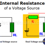
Voltage sources, whether batteries, generators, etc., are not ideal (perfect). A real voltage source is composed of an ideal voltage source in series with a resistance called internal resistance.

Full Story
Current Limiter circuit for Power Supply using transistor & resistor

Current Limiter circuit for Power Supply using transistor & resistor

  •  
  •  
  •  
  •  
  •  
  •  December 7, 2022
  •  Current Limiter circuit for Power Supply using transistor & resistor
  •  Posted by Marcel at 1:39 pm
  •  No Responses
  •  Supplies

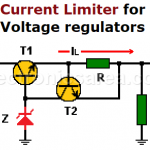
Current Limiter circuit for a Power Supply using a transistor and a resistor.

If the load current exceeds its maximum, an over current protection is needed

Full Story
Power Supply - Block Diagram (AC - DC conversion process)

Power Supply – Block Diagram (AC – DC conversion process)

  •  
  •  
  •  
  •  
  •  
  •  October 16, 2020
  •  Power Supply – Block Diagram (AC – DC conversion process)
  •  Posted by Marcel at 9:59 am
  •  No Responses
  •  Supplies

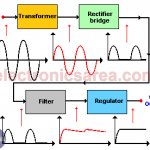
Many electronic circuits need a direct current (DC) voltage source, but what we commonly find are voltage sources of alternating current (AC). In order to achieve a direct current voltage source, the alternating current input must follow a conversion process.

Full Story
Transformerless Power Supply circuit

Transformerless Power Supply circuit

  •  
  •  
  •  
  •  
  •  
  •  September 22, 2020
  •  Transformerless Power Supply circuit
  •  Posted by Marcel at 10:31 am
  •  2 Responses
  •  Supplies

This circuit is designed to be connected to a specific circuit because it can give a maximum and minimum possible electric current

Full Story
Transistorized Voltage Regulator (Zener & Transistor)

Transistorized Voltage Regulator (Zener & Transistor)

  •  
  •  
  •  
  •  
  •  
  •  September 16, 2020
  •  Transistorized Voltage Regulator (Zener & Transistor)
  •  Posted by Marcel at 9:11 am
  •  No Responses
  •  Supplies

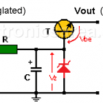
Explanation of a transistorized voltage regulator. Zener diode and transistor voltage regulator circuit diagram

Full Story
Zener diode Voltage regulator Circuit Design - Diagram

Zener diode Voltage regulator Circuit Design – Diagram

  •  
  •  
  •  
  •  
  •  
  •  
  •  September 6, 2020
  •  Zener diode Voltage regulator Circuit Design – Diagram
  •  Posted by Marcel at 8:19 am
  •  1 Response
  •  Supplies
  •  Tagged with: voltage regulator

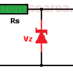
Design method. Determination of the voltage, power of the zener diode and of the limiting resistor Rs

Full Story
Voltage Regulators - Linear, Switching

Voltage Regulators – Linear, Switching

  •  
  •  
  •  
  •  
  •  
  •  September 5, 2020
  •  Voltage Regulators – Linear, Switching
  •  Posted by Marcel at 10:40 am
  •  No Responses
  •  Supplies

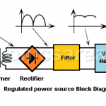
Voltage regulators (linear, switching) provide a stable and fixed voltage output to give energy to electronics circuits from an unregulated power source
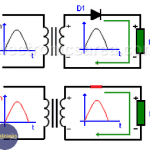
Full Story
Types of Cells / Batteries

Types of Cells / Batteries

  •  
  •  
  •  
  •  
  •  
  •  August 3, 2015
  •  Types of Cells / Batteries
  •  Posted by Marcel at 10:43 am
  •  No Responses
  •  Supplies

Types of cells / batteries. Primary batteries (non-rechargeable): Dry, mercury, alkaline. Secondary batteries (rechargeable): Nickel-Cadmium Alkaline, Lead

Full Story
How does a battery work?

How does a battery work?

  •  
  •  
  •  
  •  
  •  
  •  July 27, 2015
  •  How does a battery work?
  •  Posted by Marcel at 2:32 pm
  •  No Responses
  •  Supplies

The electric current is a flow of electrons that flow through a conductor cable. Electrons are negatively charged, and like two magnets that we want to put together, negative side with negative side or positive side with positive side, they repel.

Full Story

Most Popular

  • Audio Splitter Circuit Diagram - 1 Input - 4 Outputs
    Audio Splitter Circuit Diagram – 1 Input – 4 Outputs
  • OR and AND logic gates made with diodes
    OR and AND logic gates made with diodes
  • ON-OFF Switch circuit using a 555 timer (PCB)
    ON-OFF Switch circuit using a 555 timer (PCB)
  • Humidity sensor circuit using the 555 timer
    Humidity sensor circuit using the 555 timer

Follow Me

Twitter Facebook

Recent Posts

  • LM317T Current-limited 6V Battery Charger
  • How do I test a Zener diode? – A simple method
  • Equivalent transformer circuits (power, audio, video and RF)
  • Wirewound Resistor
  • Light detector circuit using LDR (automatic night light)
  • The Decibel – Voltage Gain & Power Gain
  • Blown Fuse Indicator Circuit using one transistor
  • Logic Probe using NOT Gates
  • Resistors in Series – The Equivalent Resistance
  • How to increase the output voltage of 78XX regulators?

Privacy
© 2015 Electronics AreaSuffusion theme by Sayontan Sinha