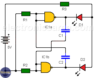
Astable multivibrator using NAND gates
This astable multivibrator uses two NAND gates of the 4 available on the 7400 TTL integrated circuit. Two LEDs are used to view the status or logic output of each gate.
In order for the circuit to start oscillating, you just need to connect the circuit to the voltage source.
– The output logic states of the gates are always opposite to those shown with the LEDs.
– LED turns on when the gate output is in a logic low state.
– When one LED is ON the other is OFF and vice versa.
The oscillation frequency of this circuit depends on the values of resistors R1 and R2 and capacitors C1 and C2.
The smaller the value of capacitors the higher the oscillation frequency, because a capacitor with a low capacitance charges faster than one with a higher value.
Note that if this circuit oscillates at a very high frequency, you may not be able to see the effect it has on the LEDs.
Resistors in series with the two LEDs is necessary to limit the current passing through them and to compensate for the voltage difference between the LED and the 5V source. It is not necessary to use a resistor for each LED because when the circuit is running, there is only one LED on at a time.
Note: Because the 7400 IC has 4 2-input NAND gates, two astable oscillators can be implemented at the same time. These oscillators can have the same or different frequencies.
List of components for the Astable Multivibrator using NAND Gates Circuit
- 1 TTL 7400 integrated circuit. (4 NAND 2-way gates) only 2 gates are used. (IC1a, IC1b)
- 2 10K resistors (R1, R2)
- 1 220 ohm resistor (R3)
- 2 100 uF (microfarads) capacitors (C1, C2)
- 2 common LEDs of any color (D1, D2)
Notes:
- The voltage source should be 5 V.
- Unused NAND gates must have their input terminals connected to 5V.
- You can vary the oscillation frequency by changing the values of capacitors and resistors./li>