Power in AC Circuit – Circuit with resistive load
If we analyze the power that a resistor consumes when a direct current flows through it (Joule’s law), it is only necessary to multiply the value of the current by the value of the voltage between its terminals. P = V x I.
The above is also true when alternating current passes through a resistor, because in these cases the current and voltage are in “phase”. This means that current and voltage have their maximum and minimum values simultaneously (the waveforms are the same. They could only differ in their amplitude)
Power in AC Circuit with reactive load (reactance)
In this case, the electric current leads or lags with respect to the voltage and its maximum and minimum values no longer coincide. The power that is obtained from the multiplication of the voltage with the current (P= I x V) is what is called an apparent power (VA).
The true power consumed depends in this case on the angle difference between the voltage and the current. This angle is represented as Θ. A circuit that has reactance means that it has a capacitor, an inductor, or both.
Power in AC Circuit
If the circuit has a capacitor
- When the source voltage goes from 0 volts to its maximum value, the source delivers power to the capacitor, and the voltage across the capacitor’s terminals increases to a maximum. The energy is stored in the capacitor as an electric field.
- When the source voltage goes from its maximum value to 0 volts, it is the capacitor that delivers power back to the source.
If the circuit has an inductor
- When the current delivered by the source goes from 0 amps to its maximum value, the source delivers power to the inductor. This energy is stored in the inductor as a magnetic field.
- When the current goes from its maximum value to 0 amps, it is the inductor that delivers power back to the source.
In these two cases, the source has an energy consumption equal to “0”, since the energy delivered by the source later returns to it. The power that returns to the source is called reactive power. So in a totally resistive circuit there is no return of energy to the source, instead, in a totally reactive circuit all the energy returns to the source.
If the circuit has an inductor, a capacitor, and a resistor:
Now it is to be assumed that in a circuit that has both types of elements (reactive and resistive), part of the power will be consumed (in the resistor) and part will be returned to the source (due to the coils and capacitors).
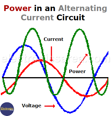
The image below shows the relationship between voltage, current, and power.
How the power in an AC circuit is obtained?
The power that is obtained from the multiplication of the current and the voltage at any moment is the instantaneous power at that moment
- When the voltage and current are positive: The source is delivering power to the circuit
- When the voltage and current are opposite (one is positive, and the other is negative), the power is negative and in this case the circuit is delivering energy to the source.
The real power consumed by the circuit will be the total power obtained with the formula P = I x V, (power delivered by the source, called apparent power) minus the power that the circuit returns (reactive power).
Note: It is a phasor subtraction, not an arithmetic one.
The real power or active power can be calculated with the following formula: P = I2 x R, where:
- P = is the value of the real or active power in watts
- I = is the current through the resistor, in amps
- R = is the value of the resistor in ohms
How to obtain the current in a circuit having resistance and reactance?
The concept of impedance is used. In this case, the impedance of this circuit is: Z = R + jX, where:
- R = resistance
- X = the reactance = XC – XL (capacitive reactance – inductive reactance)
Then:
- Z = (R2 + X2)1/2 (see: Impedance)
- I = E/Z (source voltage divided by total reactance)
Where:
- I = current in amperes
- E = source voltage
- Z = impedance calculated above
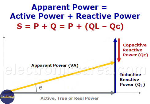
Phasor diagram of powers in an alternating current circuit
In alternating current, the sum of the power in Real (P) due to the resistive part plus the reactive power (Q), due to reactive components such as capacitors and coils, is called apparent power (VA).
S = P + Q, where Q = QL – QC (inductive reactance – capacitive reactance)
The powers in a circuit with resistances and reactances, in alternating current, can be obtained with the following formulas:
- Active Power = Real Power = P = V x I x cos(Θ) in watts (watts)
- Reactive Power = Q = V x I sin(Θ) in VAR (reactive volt-amperes)
- Apparent Power = S = V x I in VA (volt-amps)
Power in an Alternating Current Circuit
From the previous diagram, it can be seen that the apparent Power (S) is equal to the phasor sum of the Real Power (PR) plus the inductive reactive Power QL minus the reactive Power.
S = P + Q = P + (QL – Qc). A phasor addition.
Another simple way to relate these values is using the Pythagorean theorem: S2 = (P2 + Q2)
You may also like to visit: Power factor definition