Electronics Area

Electrical and Electronics Tutorials and Circuits
  • Home
  • Tutorials
    • DC Theory Tutorials
    • Alternating Current (AC)
    • Digital Electronics
  • Semiconductors
  • Circuit diagrams
    • Audio Circuits & Projects
    • Control Circuits
    • Detector Circuits and Projects
    • Power supply
    • Timer Circuits and Projects – 555 Timer
    • Op. Amp. Circuits
    • LED Circuits & Projects
    • Alarm Circuits and Projects
    • Test circuits
    • Battery chargers. Battery monitors and Projects
  • Instruments and Measurements
Half Wave Rectifier - Half-wave Rectifier. Circuit diagram

Half Wave Rectifier – Half-wave Rectifier. Circuit diagram

  •  
  •  
  •  
  •  
  •  
  •  
  •  August 31, 2020
  •  Half Wave Rectifier – Half-wave Rectifier. Circuit diagram
  •  Posted by Marcel at 5:13 am
  •  No Responses
  •  Alternating Current (AC)
  •  Tagged with: power supply, transformer

The half-wave rectifier rectification process.

Polarization of semiconductor diode in the forward and in the reverse direction. Input and output waveforms

Full Story
Transformer Structure

Transformer Structure

  •  
  •  
  •  
  •  
  •  
  •  
  •  October 4, 2019
  •  Transformer Structure
  •  Posted by Marcel at 10:56 am
  •  No Responses
  •  transf
  •  Tagged with: transformer

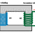
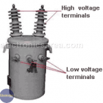
Electric Power Transformer Structure. All electric transformers, have three fundamentals parts: high voltage winding, low voltage winding and Core.

Full Story
Transformer Turn Ratio (K)

Transformer Turn Ratio (K)

  •  
  •  
  •  
  •  
  •  
  •  
  •  August 5, 2019
  •  Transformer Turn Ratio (K)
  •  Posted by Marcel at 10:32 am
  •  No Responses
  •  transf
  •  Tagged with: transformer

The transformer turn ratio (K) is the quotient value obtained by dividing the number of turns of the primary winding (N1) and the number of turns of the secondary winding (N2). Then K = N1/N2.

Full Story

Most Popular

  • Audio Splitter Circuit Diagram - 1 Input - 4 Outputs
    Audio Splitter Circuit Diagram – 1 Input – 4 Outputs
  • OR and AND logic gates made with diodes
    OR and AND logic gates made with diodes
  • ON-OFF Switch circuit using a 555 timer (PCB)
    ON-OFF Switch circuit using a 555 timer (PCB)
  • Humidity sensor circuit using the 555 timer
    Humidity sensor circuit using the 555 timer

Follow Me

Twitter Facebook

Recent Posts

  • How do I test a Zener diode? – A simple method
  • Equivalent transformer circuits (power, audio, video and RF)
  • Wirewound Resistor
  • Light detector circuit using LDR (automatic night light)
  • The Decibel – Voltage Gain & Power Gain
  • Blown Fuse Indicator Circuit using one transistor
  • Logic Probe using NOT Gates
  • Resistors in Series – The Equivalent Resistance
  • How to increase the output voltage of 78XX regulators?
  • Mesh Current Method – Steps to follow – Example

Privacy
© 2015 Electronics AreaSuffusion theme by Sayontan Sinha