Home / Circuits / Battery related /
What is a current-limited 6 V battery charger?
This current-limited 6 V battery charger is a circuit designed to charge a 6-volt battery using the well-known LM317T voltage regulator. The LM317T is used to control the maximum current at which the battery can be charged.
The current in this battery charger is limited by switching between constant current and constant voltage states. The operation of these two states is explained below. See the picture below.
Operation of the current-limited battery charger
For a battery, that demands a low current (constant current charging)
When the battery demands a low current, the voltage drop across the 1 Ω resistor is too low to activate the NPN transistor (Q1). The transistor remains in cutoff mode (i.e., there is no current conduction between the collector and emitter terminals). For all intents and purposes, Q1 is effectively nonexistent.
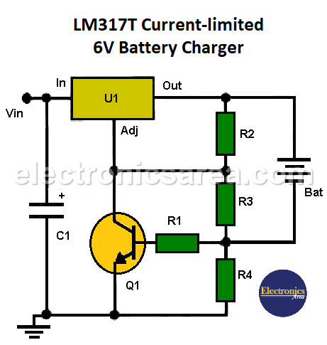
Current-limited 6 V battery charger
For a battery, that demands a hight current (constant voltage charging)
A constant voltage will be present between the battery terminals, which will be regulated by the voltage divider consisting of resistors R2, R3, and R4.
When the current charging the battery exceeds its maximum value, there will be enough voltage between the terminals of the 1-ohm resistor (R4) to make the transistor conduct. The transistor Q1 forces the Adj pin of the LM317 voltage regulator (U1) to approach the ground voltage (0 volts).
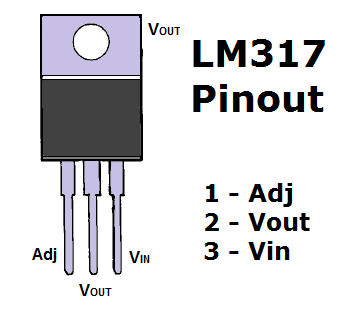
Pin layout and package of the LM317T voltage regulator.
In order to drive the transistor, 600 mA of current must pass through the 1-ohm resistor. Using Ohm’s law (V = I – R), we can calculate the base-emitter voltage. V(be) = (600 mA)(1 Ω) = 0.6 V. This 0.6 V is what is needed to drive transistor Q1.
This limits the maximum current at which the battery can be charged. The maximum charging current can be adjusted by changing the value of resistor R4.
Example: If R4 = 0.5 Ω, the maximum current will be approximately I_(max) = 0.6 V / 0.5 Ω = 1.2 A.
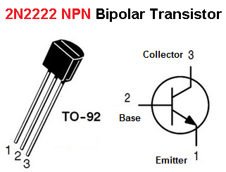
Pin layout and package of the NPN 2N2222 bipolar transistor.
Notes:
- This battery charger can be powered by an input voltage ranging from 9 to 40 volts.
- The electrolytic capacitor C1 filters transient signals at the input of the current limiter.
Current-limited 6V battery charger components list
- 1 x LM317N variable voltage regulator (U1)
- 1 x NPN 2N2222 bipolar transistor or similar (Q1)
- 1 x 1000 µF/50 V or more electrolytic capacitor (C1)
- 1 x 100 Ω resistor (R1)
- 1 x 240 Ω resistor (R2)
- 1 x 1.1 kΩ resistor (R3)
- 1 x 1 Ω, 1/2 W resistor (R4)
- 1 heat sink for the LM317 regulator
You may also like the 12V battery charger auto shutdown circuit


")